Rachet-type tensioner

a tensioner and ratchet technology, applied in the direction of belts/chains/gearings, mechanical instruments, belts/chains/gearings, etc., can solve the problems of shortening the useful life of the chain, affecting the sliding direction and reducing the sliding ability of the ratchet element relative to the guide surface, so as to reduce the excessive tension quickly

Inactive Publication Date: 2014-05-27
TSUBAKIMOTO CHAIN CO
View PDF9 Cites 3 Cited by
  • Summary
  • Abstract
  • Description
  • Claims
  • Application Information

AI Technical Summary

Benefits of technology

[0012]The invention aims at solving the aforementioned problems by providing a ratchet-type tensioner capable of restricting setback of a plunger by engaging rack teeth on the plunger by ratchet teeth of a ratchet member slidable in the tensioner housing, wherein the plunger is allowed to set back quickly when the tension of the transmission medium is excessive, thus reducing the load and noise of the transmission medium caused by the excessive tension.
[0013]The invention also aims at preventing the plunger from setting back when hydraulic pressure within the high-pressure oil chamber is too low to counteract the reaction force exerted by the transmission medium, thereby reducing the noise caused by the setback of the plunger.

Problems solved by technology

If the plunger of the tensioner advances excessively when a timing chain becomes loose due to elongation as a result of fluctuations in tension or thermal expansion caused by changes in engine temperature, the restriction on retraction of the plunger due to operation of the ratchet mechanism can result in prolonged operation of the chain under excessive tension, which can result in noise as well as excessive forces that can shorten the useful life of the chain.
However, the reaction force imparted to the plunger as a result of excessive tension in the chain can cause the ratchet element to become inclined slightly relative to its sliding direction.
When point contact occurs, the slidability of the ratchet element relative to the guide surface is compromised, and the ratchet element no longer moves smoothly in the direction in which its teeth disengage the rack teeth.
In this tensioner, there is also a problem that, on starting the engine, the hydraulic pressure in the tensioner can be insufficient to prevent setback of the plunger because of entry of air into the high pressure oil chamber while the engine is stopped.

Method used


Image

  • Rachet-type tensioner
  • Rachet-type tensioner
  • Rachet-type tensioner

Examples


Embodiment Construction

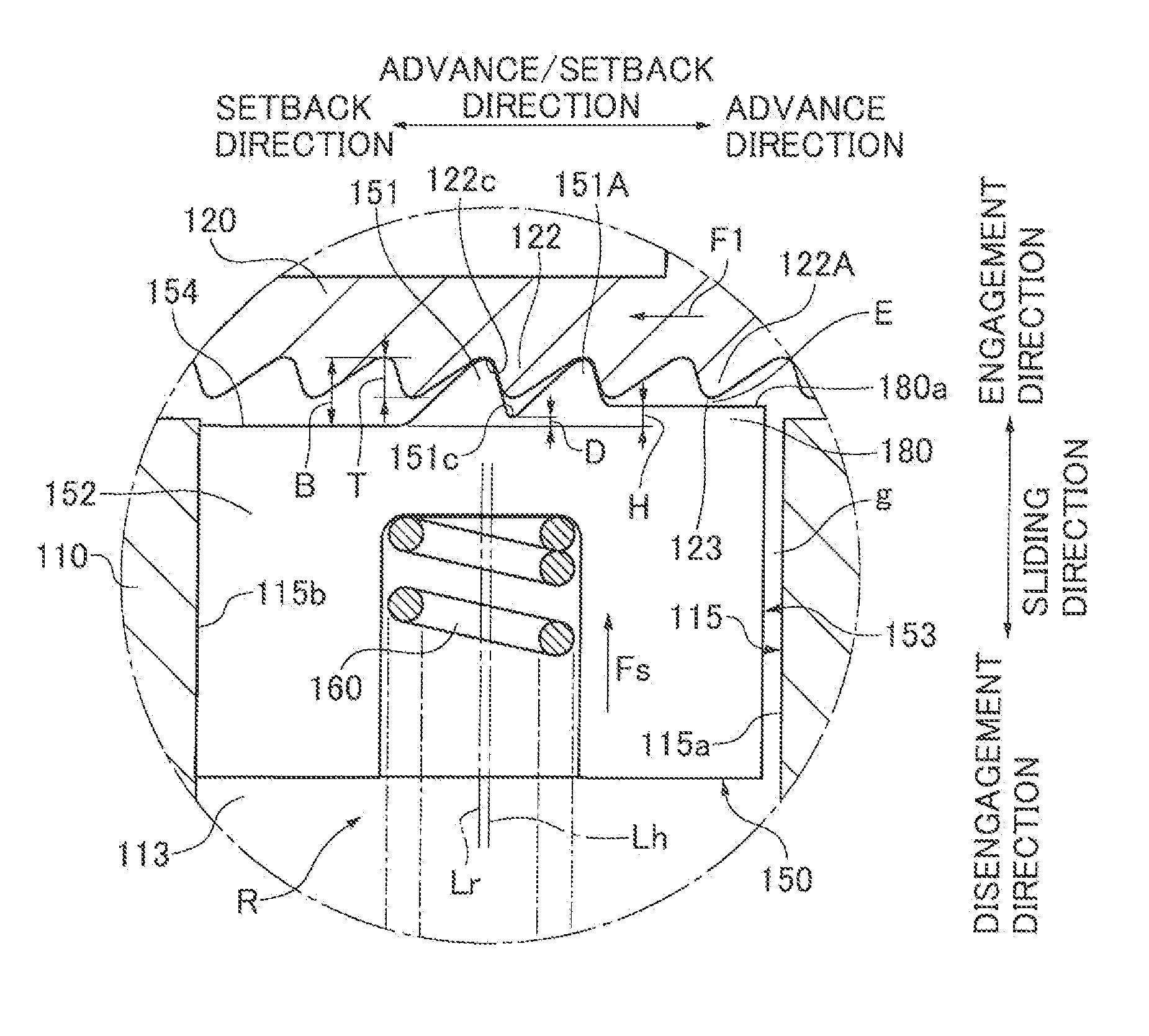
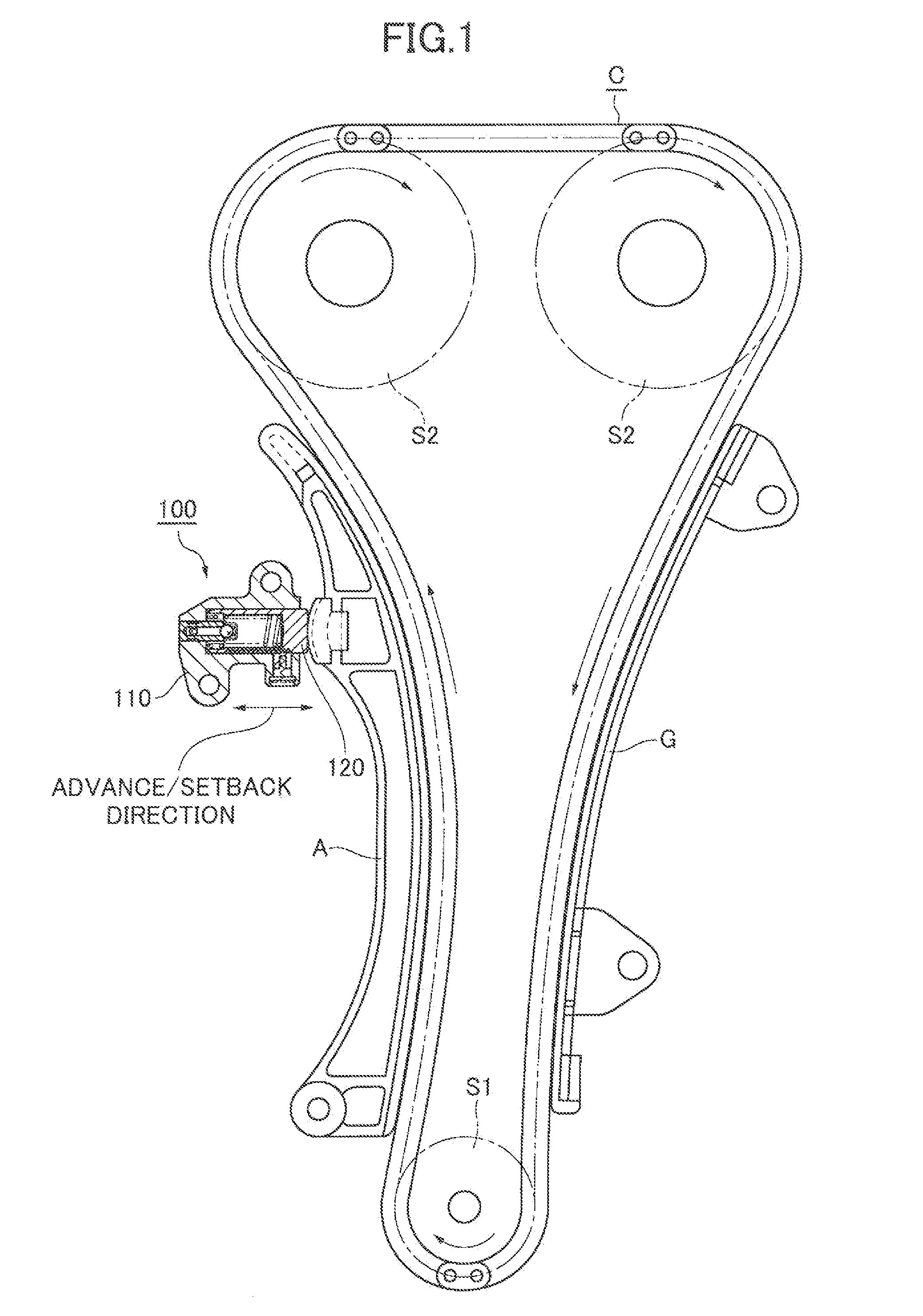
[0055]The ratchet-type tensioner 100 in FIG. 1 is attached to an engine block (not shown) adjacent the slack side of the endless engine timing chain C, i.e., the span of the timing chain that travels from the engine crankshaft sprocket S1 toward one of two engine camshaft sprockets S2.

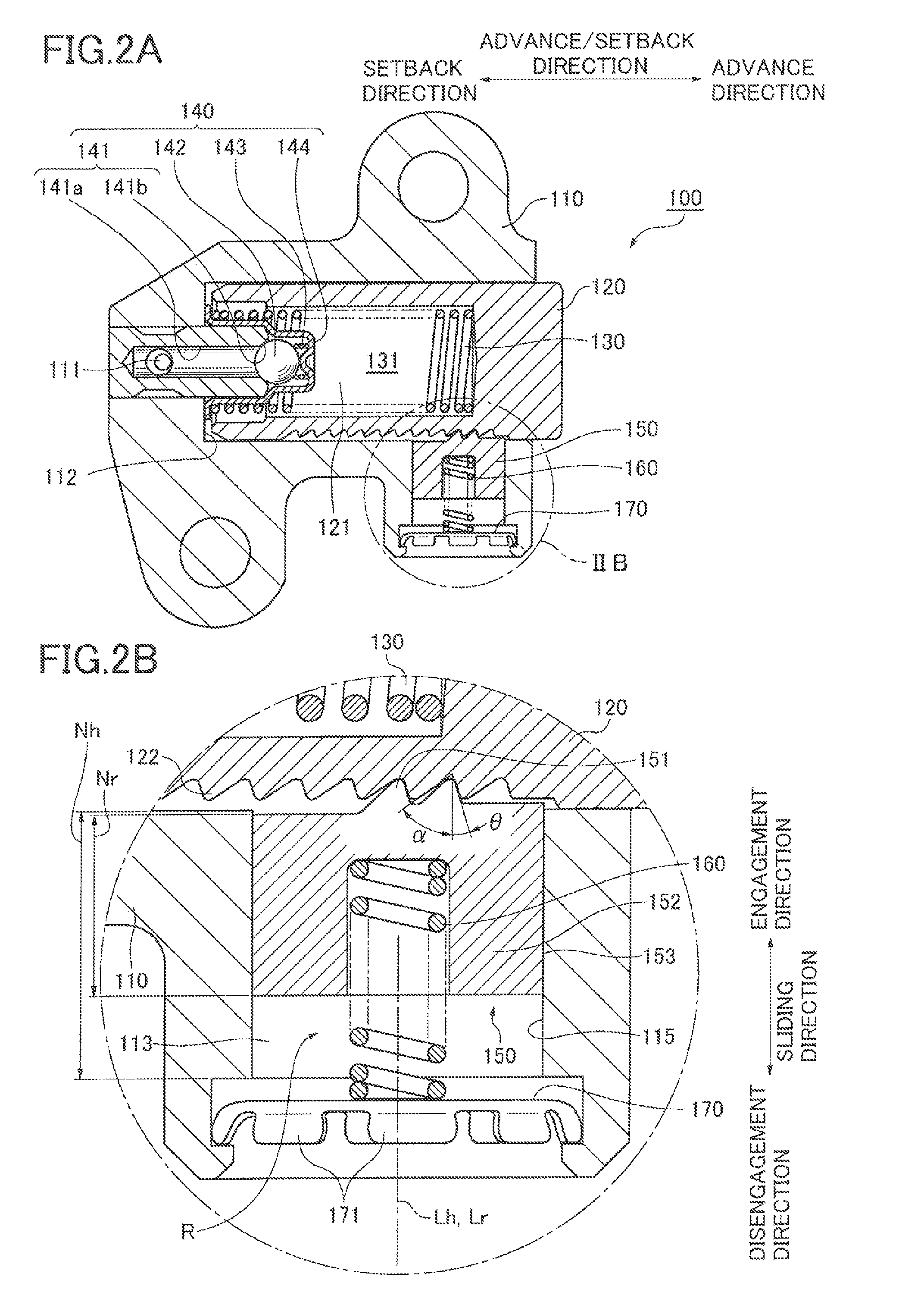
[0056]The tensioner 100 has a housing 110 and a plunger 120 that projects out of the housing and is movable in an advancing direction toward the chain and in a setback, or retracting, direction away from the chain. The plunger 120 applies tension to the slack side of the chain through a movable lever A on which the chain slides. The lever is pivotably supported on the engine block, and is in sliding engagement with the part of the chain on the outside of the loop formed by the chain.

[0057]A stationary guide G is in engagement with the tension side of chain C, i.e., the span that travels from one of the camshaft sprockets S2 toward the crankshaft sprocket S1. This guide G is also in sliding engagement w...


PUM


Abstract

A ratchet-type tensioner capable of restricting setback of a plunger includes a ratchet mechanism that allows setback of the plunger by sliding a ratchet element in a disengaging direction to disengage ratchet teeth from rack teeth when a reaction force acts on the plunger as a result of excessive chain tension. The ratchet element is slidable in a ratchet-receiving hole, and an inclination suppressing structure that prevents the ratchet element from becoming skewed in the ratchet receiving hole to an extent such that its forward end contacts one side of the hole while its rearward end contacts the opposite sides of the hole.

Description

CROSS REFERENCE TO RELATED APPLICATIONS[0001]This application claims priority from Japanese Patent Application No. 2011-044378, filed on Mar. 1, 2011. The disclosure of Japanese Patent Application No. 2011-044378 is incorporated by reference.FIELD OF THE INVENTION[0002]The invention relates to a ratchet-type tensioner for applying tension to an endless, flexible, transmission medium such as a timing chain or timing belt engaged with sprockets or similar rotating members to transmit power. A ratchet-type tensioner can be used, for example, to maintain tension in a timing chain used to drive camshafts and other components of an internal combustion engine.BACKGROUND OF THE INVENTION[0003]A typical ratchet-type tensioner includes a plunger slidable in a plunger-accommodating hole in a tensioner housing. The plunger is biased in its advancing, i.e., protruding, direction, and abuts a flexible transmission medium directly, pr through a device such as a pivoted tensioner lever, to apply te...

Claims


Application Information

Patent Timeline
Patent Type & Authority Patents(United States)
IPC IPC(8): F16H7/08
CPCF16H7/0848F16H2007/0853F16H2007/0859F16H2007/0812
Inventor ISHII, AKIRAMAEDA, MUNEHIROYOSHIDA, OSAMUKUREMATSU, YUJI
Owner TSUBAKIMOTO CHAIN CO
Why Eureka
Try Eureka