
Systems and methods for decompression and elliptical traction of the cervical and thoracic spine

a cervical and thoracic spine technology, applied in the field of spinal decompression and elliptical traction systems and methods, can solve the problems of limiting the normal canaliculus seepage and imbibition of adjacent fluids via the vertebral end, further loss of mobility, degeneration and possible nerve damage, etc., to reduce hyper-kyphosis of the upper thoracic spine, and reduce hyper-kyphosis of the upper

Active Publication Date: 2014-07-01
GRAHAM RICHARD A
View PDF80 Cites 50 Cited by
  • Summary
  • Abstract
  • Description
  • Claims
  • Application Information

AI Technical Summary

Benefits of technology

The patent describes a traction device for improving spinal health by applying a forward curve to the cervical spine and reducing hyper-kyphosis of the upper thoracic spine. The device includes a frame and two inflatable bladders that are positioned on the user's neck and upper toracic region, respectively. The bladders are designed to expand in different directions to provide traction and decompression to the spine. The device can be easily secured to the user's head and can be adjusted to apply pressure to the cervical spine or the upper toracic spine. The technical effects of the invention include improved spinal health, reduced hyper-kyphosis of the upper toracic spine, and reduced pain and discomfort for the user.

Problems solved by technology

Such traction tends to straighten the cervical spine and often results in TMJ pain.
Additionally, individuals with lost or reversed (buckled) cervical spinal curves eventually exhibit a significant loss of natural joint movement, further limiting the normal canaliculus seepage and imbibition of adjacent fluids via vertebral end plates and annuli.
Without such nutrient rich fluids the discs continue to dehydrate, further weakening the discs, resulting in a further loss of mobility, degeneration and possible nerve damage.
These forces, powerful enough to separate the spinal joints, are unfortunately antithetical to the natural geometry and biomechanics of the human cervical spine.

Method used


Image

  • Systems and methods for decompression and elliptical traction of the cervical and thoracic spine
  • Systems and methods for decompression and elliptical traction of the cervical and thoracic spine
  • Systems and methods for decompression and elliptical traction of the cervical and thoracic spine

Examples


Embodiment Construction

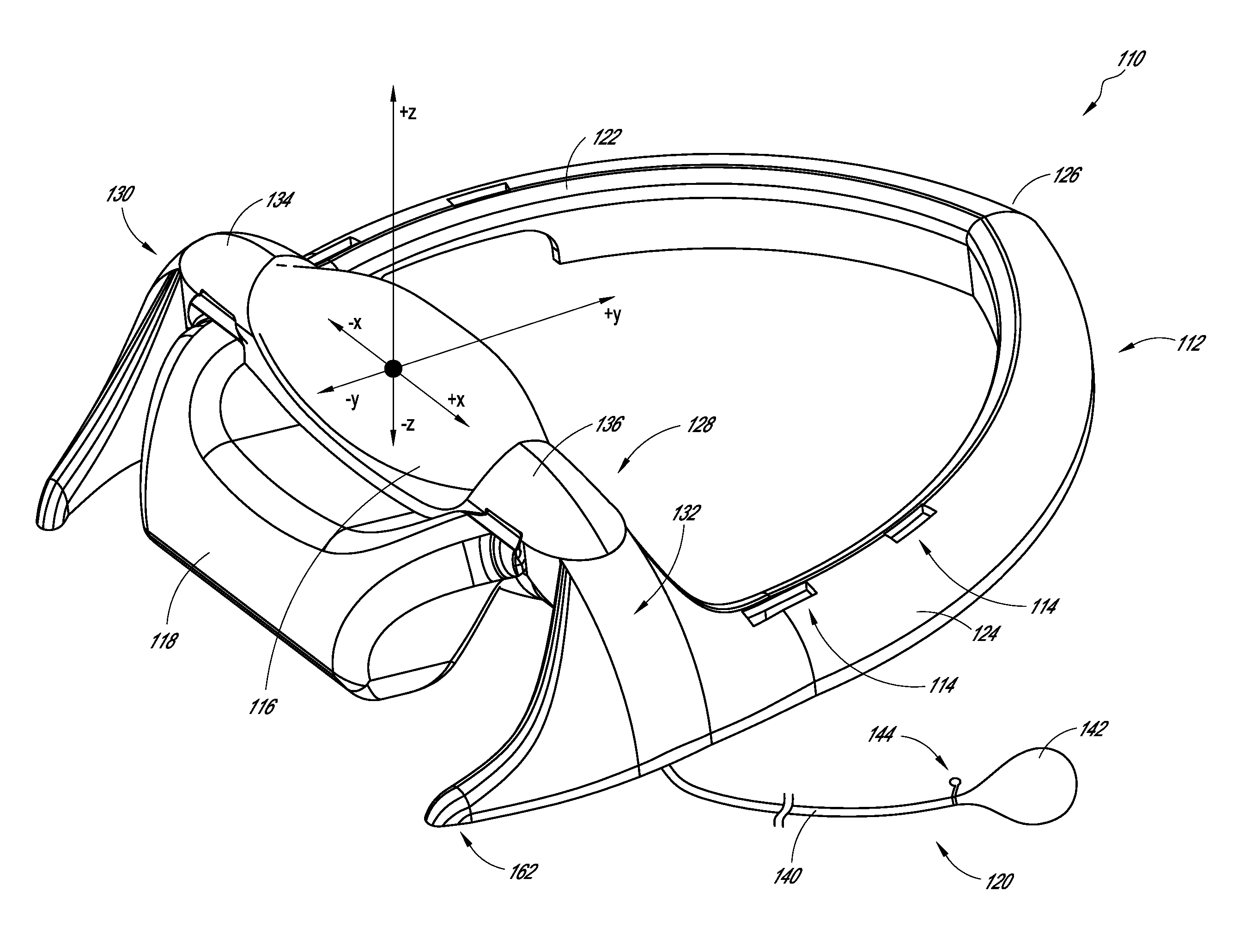
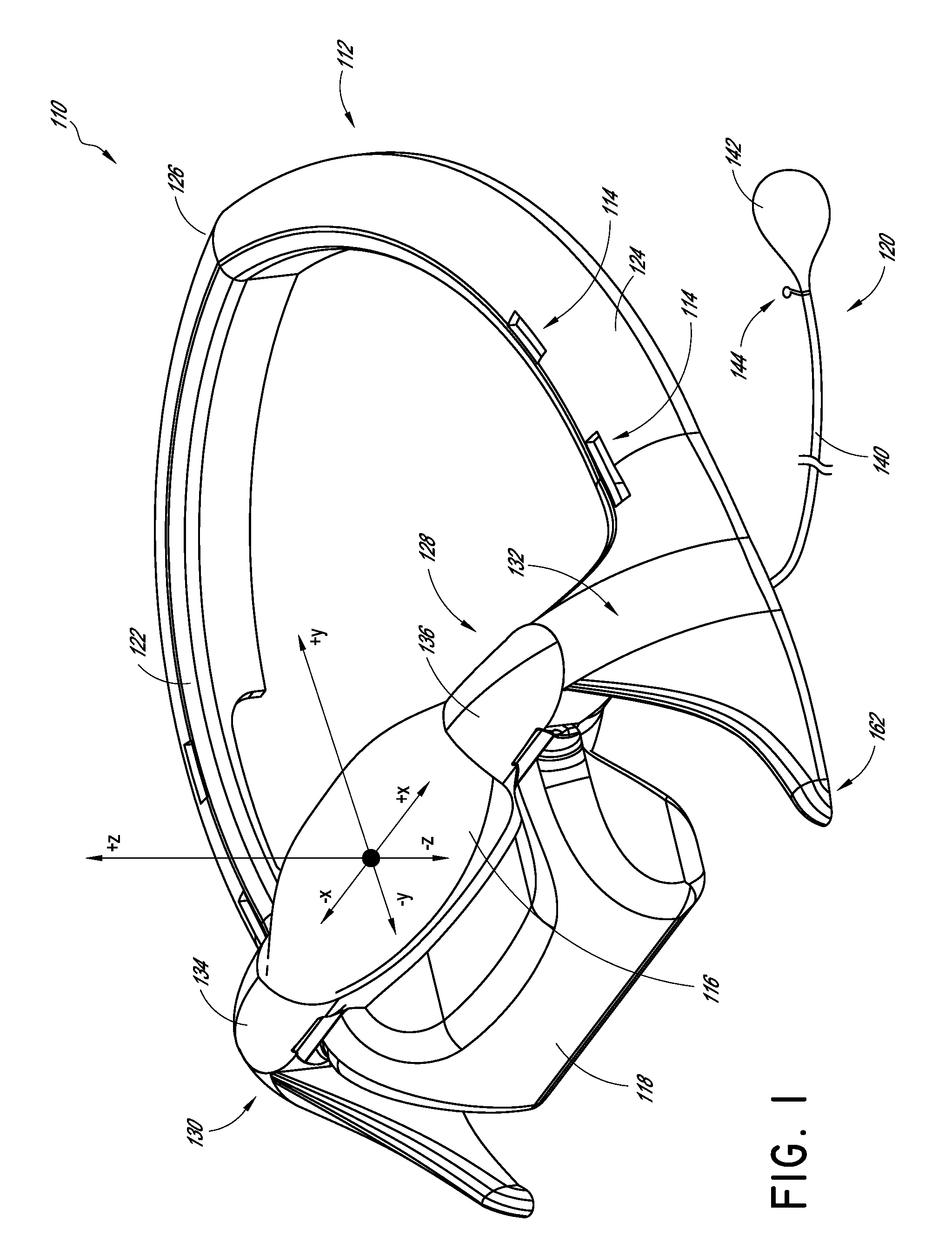
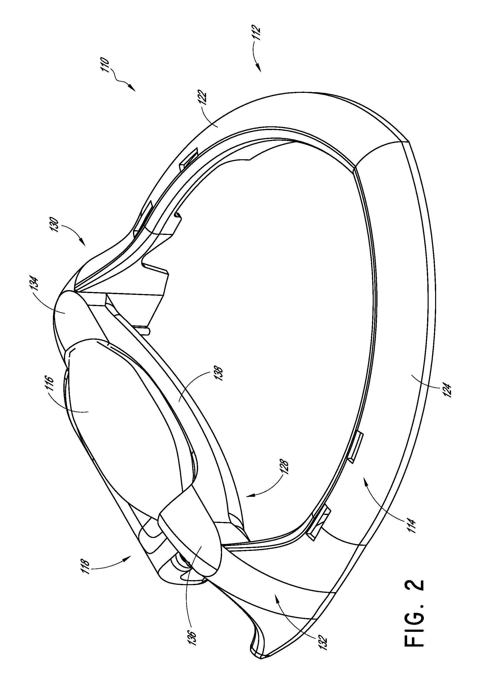
[0041]According to some preferred embodiments, the devices, systems and methods described herein relate to a decompression and traction system for imparting the desired lordotic shape into the cervical region of the spine and counteracting hyper-kyphosis of the area of the upper thoracic spine. Some systems can be used to work the spine and surrounding tissue to promote fluid and cellular exchange in and around the intervertebral discs.

[0042]In some embodiments, the device comprises a frame, a first substantially ellipsoidal inflatable bladder transversely in a neck support cradle carried by the frame, a second inflatable bladder supported on the neck support cradle carried by the frame and configured to provide a force vector against the upper thoracic spine when inflated, one or more restraining straps for securing the device to the user's head such that the first and second bladders are disposed against the back of the neck under a stress point in the cervical spine and against t...


PUM


Abstract

A traction device comprises a frame, a first bladder portion, a second bladder portion, a spacer, and a pump. The first bladder expands in an outward direction a distance greater than in a transverse direction. The second bladder expands in an angular direction. The second bladder is positioned generally below and to the side of the first bladder. Upon expanding in the outward direction, the first bladder bears against the back of the user's neck. Upon expanding in the transverse direction, the first bladder applies an angular traction to the cervical spine. Upon expanding in the angular direction, the second bladder bears angularly against the back of the user's upper thoracic region.

Description

CROSS-REFERENCE TO RELATED APPLICATIONS[0001]Any and all applications for which a foreign or domestic priority claim is identified in the Application Data Sheet as filed with the present application, are hereby incorporated by reference under 37 CFR 1.57.BACKGROUND[0002]1. Field of the Invention[0003]Disclosed herein are spinal decompression and traction systems and methods related to the field of spinal treatment. More particularly, certain embodiments disclosed herein relate to cervical and thoracic spinal decompression and traction systems having a plurality of inflatable bladders and methods of use that maintain a normal lordotic curve and counter hyper-kyphosis of the upper thoracic spine.[0004]2. Description of the Related Art[0005]Cervical pain is one of the most common health-related complaints. When there are no neurological deficits, symptomatic relief of pain is often sought with either non-steroidal analgesics, or various physical therapy modalities, including cervical t...

Claims


Application Information

Patent Timeline
IPC IPC(8): A61H1/02A61F5/042
CPCA61F5/05816A61H1/02A61F5/055A61F5/042A61H1/0292A61H1/0296A61H9/0078A61H2201/0173A61H2201/1238A61H2201/1253A61H2201/1607A61H2203/0456
Inventor GRAHAM, RICHARD, A.
Owner GRAHAM RICHARD A
Learn More