Printer with paper cutter and control method for the same

a technology of paper cutter and paper cutter, which is applied in the direction of typewriters, printing, other printing apparatuses, etc., can solve the problems of operator and access cover not being able to open and close, and achieve the effect of limiting the movement of the cover, ensuring safety and ensuring safety

Active Publication Date: 2014-07-15
SEIKO EPSON CORP
View PDF16 Cites 4 Cited by
  • Summary
  • Abstract
  • Description
  • Claims
  • Application Information

AI Technical Summary

Benefits of technology

[0023]When the access cover opens while the movable knife protrudes from the cover in this aspect of the invention, the movable knife disposed to the cover and the engaging member disposed on the printer case side interfere and limit movement of the cover. More specifically, the access cover cannot be opened when the movable knife is protruding from the cover. As a result, because the movable knife protruding from the access cover will not move with the cover and be exposed outside the printer case, safety can be assured when opening and closing the access cover. In addition; because the cover can be opened when the fixed knife is displaced to the retracted position where the cutting edge is opposite the recording paper guide member, safety can be assured when the operator opens the access cover and replaces the roll paper.

Problems solved by technology

More specifically, the access cover cannot be opened when the movable knife is protruding from the cover.
Therefore, if the automatic cutter fails while cutting the recording paper, for example, and the movable knife is effectively locked in a position between the cutting standby position and the end-of-cutting position, the operator cannot open the cover because the movable knife is protruding from the cover.

Method used


Image

  • Printer with paper cutter and control method for the same
  • Printer with paper cutter and control method for the same
  • Printer with paper cutter and control method for the same

Examples


Embodiment Construction

[0033]A preferred embodiment of a roll paper printer with a paper cutter according to the present invention is described below with reference to the accompanying figures.

General Configuration

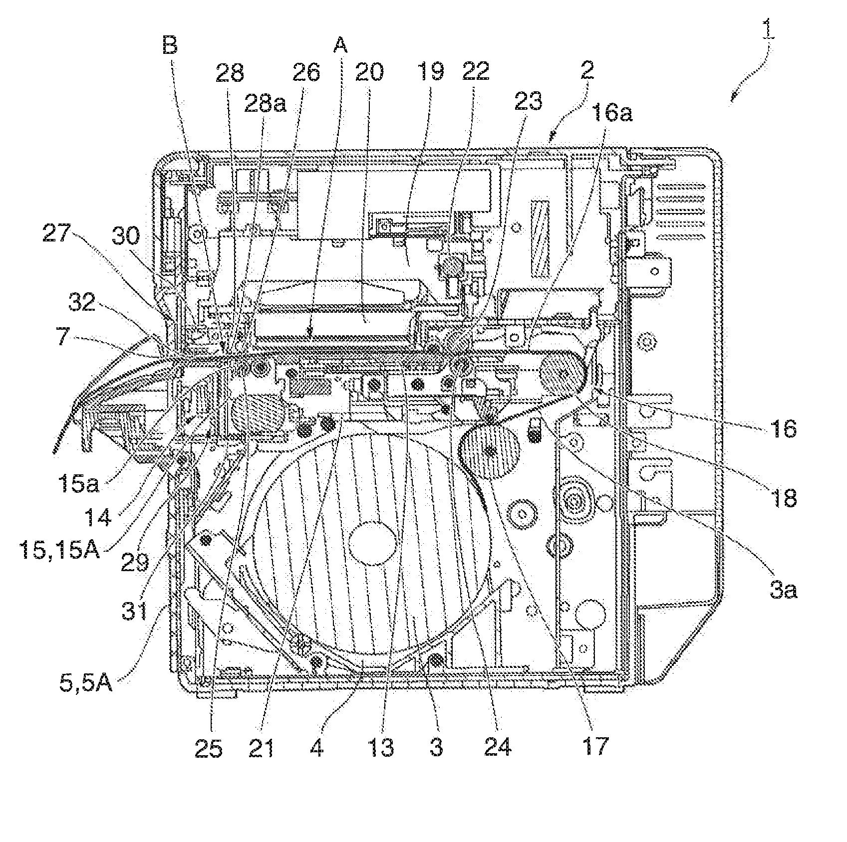
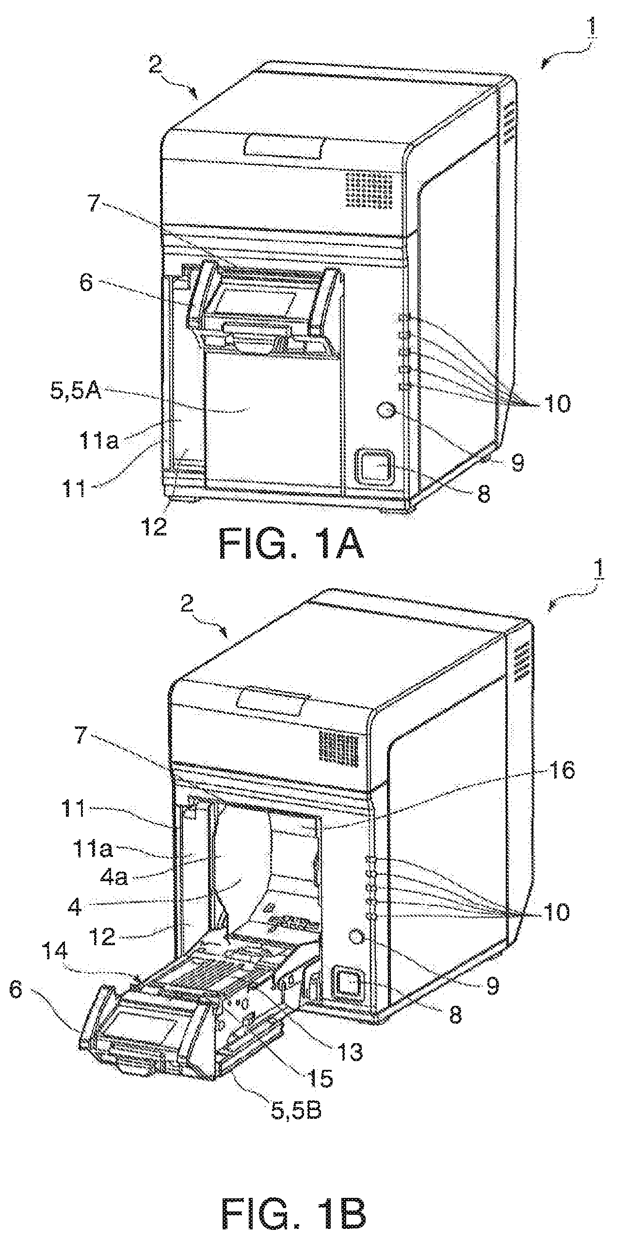
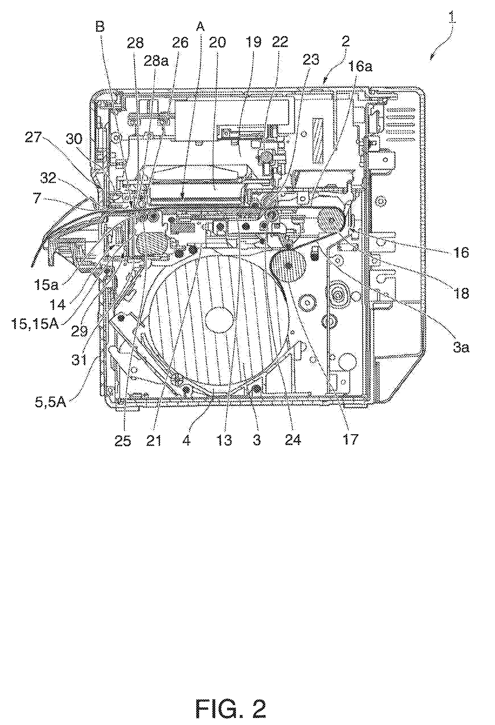
[0034]FIGS. 1A and 1B show external oblique views of a roll paper printer with a paper cutter according to a preferred embodiment of the invention. FIG. 1A shows the printer when the roll paper compartment cover is closed, and FIG. 1B shows the printer when the cover is open. The roll paper printer with cutter 1 is an inkjet printer that prints in color on a continuous web of recording paper pulled from a paper roll, and as shown in FIG. 1A has a rectangular box-shaped printer case 2.

[0035]An opening 4a to the roll paper compartment 4 in which the roll paper 3 is stored (see FIG. 2) is formed in the front middle part of the printer case 2, and this opening 4a is closed by a access cover 5 that is attached to the printer case 2 so that the access cover 5 can open and close. A recording paper exit...


PUM


Abstract

A printer has an automatic cutter and a recording paper guide member. The automatic cutter includes a fixed knife attached to the printer case and a movable knife attached to an access cover. The movable knife is attached to the open side of the access cover relative to the fixed knife. The recording paper guide member is disposed to the printer case at a position closer to the open side of the access cover than the movable knife. The movable knife protruding to the fixed knife side and the recording paper guide member interfere if the access cover is opened when the movable knife has moved to the cutting start position. As a result, because movement of the access cover is limited and the access cover will not open, the movable knife protruding to the fixed knife side is not exposed outside the printer case.

Description

[0001]This application claims priority under 35 U.S.C. §119 to Japanese Patent Application No. 2009-251743 filed on Nov. 2, 2009, the entire disclosure of which is expressly incorporated by reference herein.BACKGROUND[0002]1. Technical Field[0003]The present invention relates to a printer with a paper cutter of which the fixed knife is attached to the printer frame and the movable knife is attached to an access cover that is attached to the printer frame so that the access cover can open and close. More particularly, the invention relates to a printer with a cutter that assures safety when opening and closing the cover to which the movable knife is attached.[0004]2. Related Art[0005]Roll paper printers with a paper cutting mechanism convey the web of recording paper pulled from a paper roll through a paper feed path from the roll paper compartment passed the printing position and cutting position to the recording paper exit. A print head prints on the recording paper at the printing...

Claims


Application Information

Patent Timeline
Patent Type & Authority Patents(United States)
IPC IPC(8): B41J11/00B41J11/70
CPCB41J11/70B41J3/4075
Inventor SHIROTORI, MOTOYOSHI
Owner SEIKO EPSON CORP
Why Eureka
Try Eureka