Hydrocarbon fueled-electric series hybrid propulsion systems

a hybrid propulsion system and hydrocarbon fuel technology, applied in the direction of propulsion by batteries/cells, capacitors, electric devices, etc., can solve the problems of increasing the complexity of the battery management system, limiting the design feature of the present day battery technology of the diesel-electric series hybrid propulsion system, and not very efficient use of fossil fuels in the conventional class 8 dot vehicle ic engine drive train. , to achieve the effect of improving the mileage performance of hydrocarbon fuel, reducing particul

Active Publication Date: 2014-07-22
EPOWER ENGINE SYST
View PDF55 Cites 54 Cited by
  • Summary
  • Abstract
  • Description
  • Claims
  • Application Information

AI Technical Summary

Benefits of technology

[0006]In contrast, most electrical devices presently available have a relatively high efficiency range in their conversion of electrical power to mechanical power, e.g., from 92 to 97 percent. By removing the IC engine drive motor in a motor driven vehicle and using an external power source to supply power to an electric drive motor, greater fuel efficiencies may be obtained from a given fossil fuel. Operating the power source at an optimal power curve and rpm setting, while producing an electrical current to be used by the drive motor and controlling the current through a computer driven motor controller, may result in optimal efficiencies compared to typical IC engine drive trains.
[0012]There is therefore a need to provide hydrocarbon fueled-electric series hybrid propulsion systems which maintain a constant torque and speed to the differential which mimics an automatic transmission without the associated mechanical energy losses of such transmissions and the associated fluid power transfer losses, and without causing driver fatigue.
[0014]There is therefore a further need to provide a hydrocarbon fueled-electric series hybrid propulsion system which eliminates the Jake brake and accomplishes the same slowing of a vehicle as the Jake brake but doing so electronically with very little or no noise.
[0017]In an embodiment of the invention, when the brakes are applied or in a coasting situation, the AC drive motor in conjunction with the AC / DC controller produces a DC current while providing regenerative braking. A portion of this power is used to keep the DC battery packs at an approximately 80 percent charge level, and the remainder or excess available DC current may be sent to various electrical systems such as a hydrogen generator, a hydraulic accumulator charging system, or other useful devices. In the case of a hydrogen generator, electrolysis of water is used to produce hydrogen gas that may then be injected into the hydrocarbon fueled engine to create additional power to the AC generator which, in turn, provides an AC current to the electric drive motor. The combining of hydrogen gas as a fuel admixture within the hydrocarbon fueled engine improves the mileage performance of the hydrocarbon fuel and reduces particulate emissions.
[0018]The electrical generation platform of the present invention provides ample DC current to produce usable amounts of hydrogen for injection into the hydrocarbon fuel injection system. When hydrogen is added to a fuel admixture in a constant rpm hydrocarbon fueled engine, fuel ignition timing issues are easily handled. This can result in as much as a 30 or 40 percent increase in fuel mileage with a cleaner burning engine and without the timing issues related to an IC engine operating at varying rpm modifications and torque ranges.

Problems solved by technology

Conventional class 8 DOT vehicle IC engine drive trains are not very efficient in their use of fossil fuels for producing mechanical energy, e.g., efficiency is 38 percent or less.
However, present day battery technology is typically the limiting design feature of diesel-electric series hybrid propulsion systems.
These exotic materials, while providing some benefit to the electric propulsion system, are expensive and add to the complexity of the battery management system.

Method used


Image

  • Hydrocarbon fueled-electric series hybrid propulsion systems
  • Hydrocarbon fueled-electric series hybrid propulsion systems
  • Hydrocarbon fueled-electric series hybrid propulsion systems

Examples


example 1

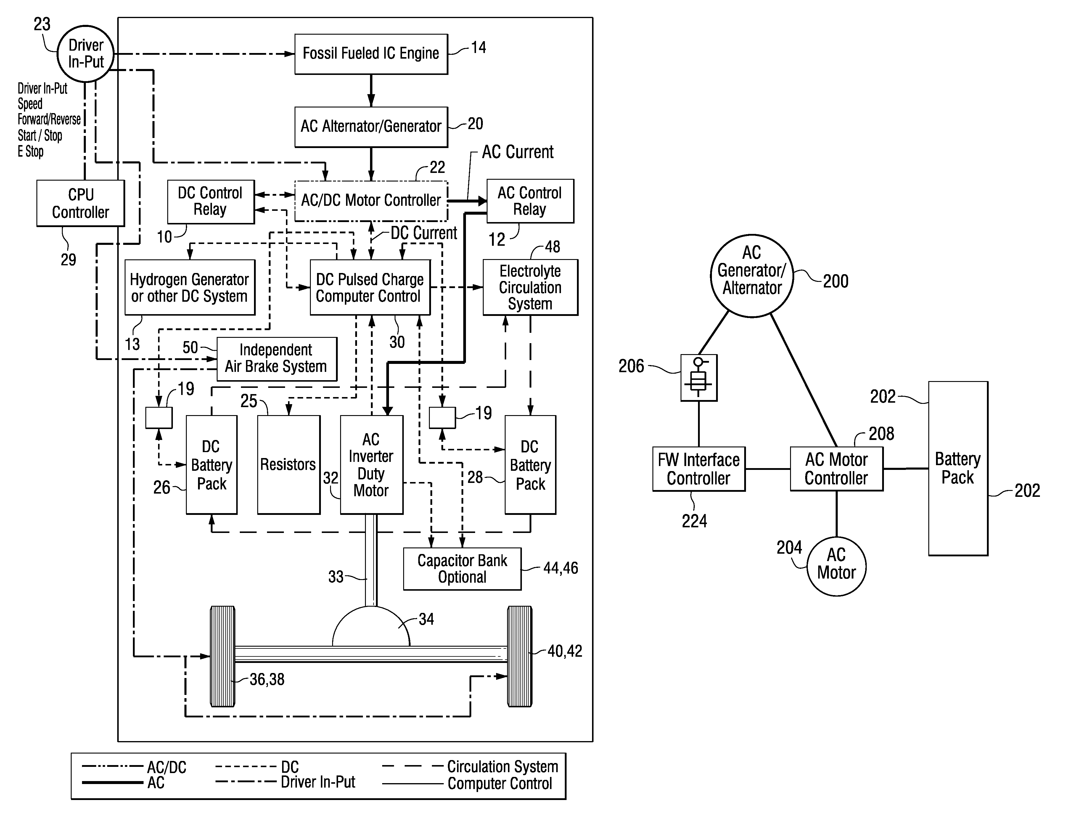
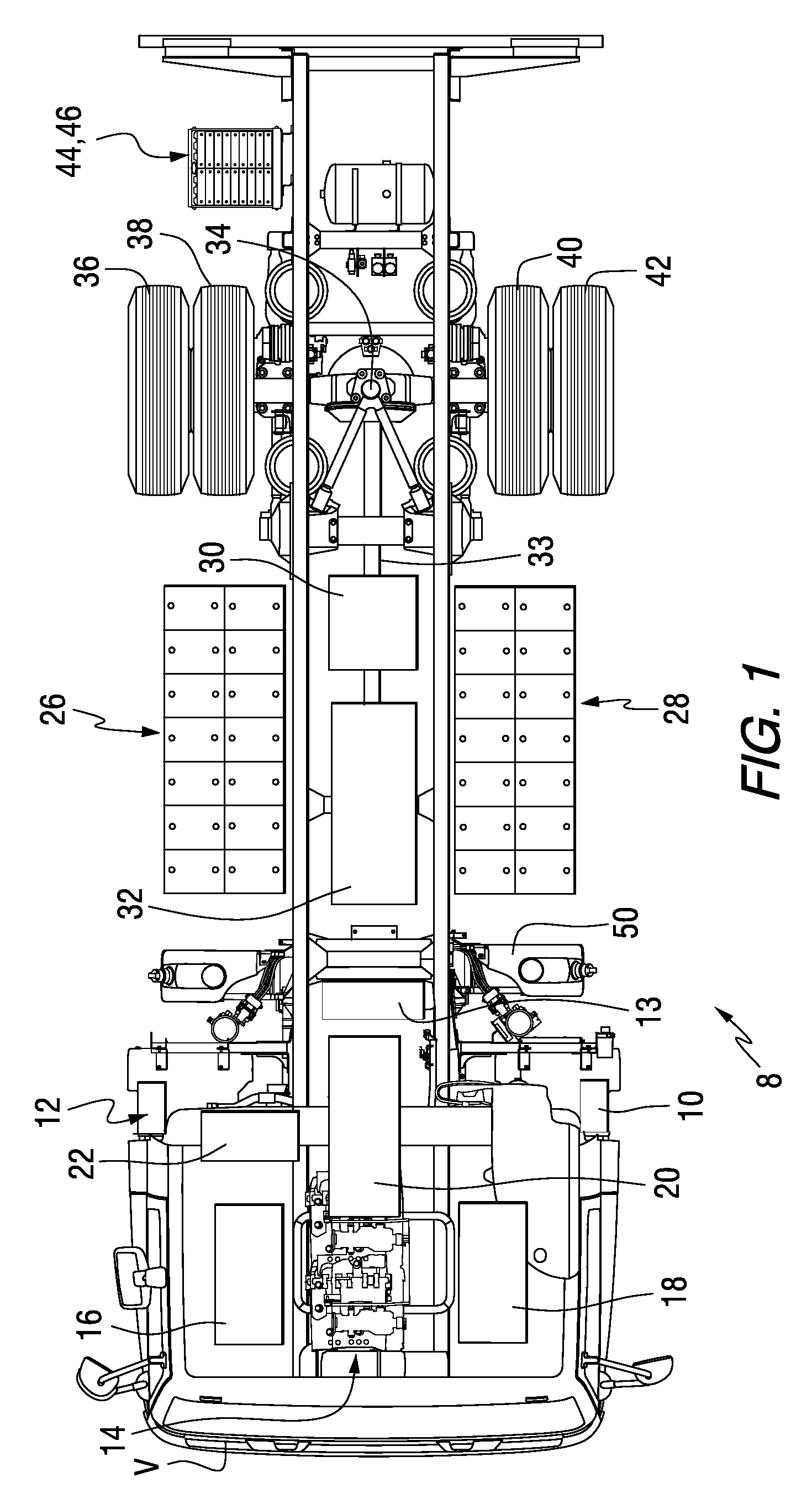
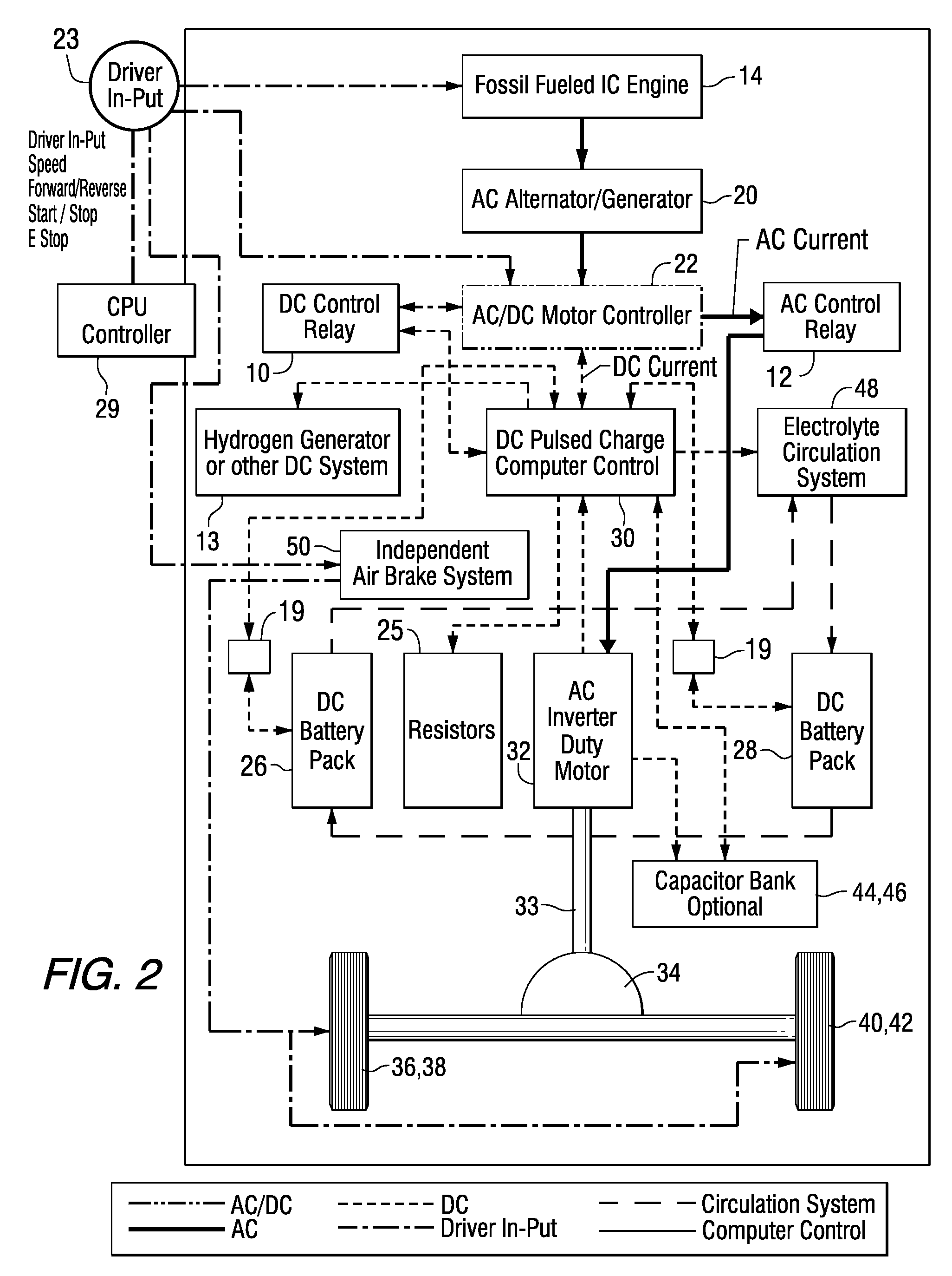
[0100]A 1989 Mack truck T was converted from a conventional diesel engine type truck to a hydrocarbon fueled electric series hybrid propulsion system 8 of the present invention. Step 1 is the removal of unnecessary components in the 1989 Mack truck T. In Step 2, the radiator, engine, transmission, fuel tanks and drive shaft of the 1989 Mack truck are removed for the conversion process. Step 3 is the installation of the AC electric motor 32 and drive shaft 33. An example of an AC electric motor 32 is available under the designation L1431A Inverter Duty manufactured by Reliance Elect. Step 4 is the alignment of the drive train with the rear differential 34. In Step 5, a gen-set GS is readied for installation. Step 6 is the installation of the diesel engine 14 and AC generator 20. An example of a hydrocarbon fueled IC engine 14 is available under Model No. 4045T manufactured by John Deere. An example of an AC generator 20 is available under Model No. 363PSL3127 manufactured by Marathon...


PUM


Abstract

A hybrid propulsion system for powering vehicles such as class 8 DOT classified semi-tractor trucks under normal load conditions and at highway speeds comprises an internal combustion engine, an AC generator powered by the engine, DC battery packs, an AC / DC controller, and an AC electric motor driving the drive train of the vehicle. The AC generator and the DC battery packs provide input to the AC / DC controller, which, in turn, converts the DC input from the DC battery packs via a DC circuit to AC so that the output from the AC / DC controller to the electric motor is AC for powering the vehicle. The DC battery packs may comprise thin plate flooded lead acid cells and may be connected in series, in parallel or a combination thereof. Vehicles may be retrofitted to incorporate the propulsion system.

Description

CROSS-REFERENCE TO RELATED APPLICATION[0001]This application claims the benefit of U.S. Provisional Patent Application Ser. No. 61 / 297,094 filed Jan. 21, 2010, which is incorporated herein by reference.FIELD OF THE INVENTION[0002]The present invention relates to hydrocarbon fueled-electric series hybrid propulsion systems for powering vehicles, and more particularly relates to such propulsion systems for powering heavy vehicles such as class 8 DOT classified semi-tractor trucks under normal load conditions and at highway speeds.BACKGROUND INFORMATION[0003]A hybrid electric vehicle (HEV) is a vehicle that is powered by an electric motor and an internal combustion (IC) engine, including diesel or other hydrocarbon or fossil fueled engines. In a diesel-electric series hybrid propulsion system, the diesel engine is not directly linked to the transmission for mechanical drive power. Rather, the energy produced from the IC engine is converted to electric power by a generator, which re-cha...

Claims


Application Information

Patent Timeline
Patent Type & Authority Patents(United States)
IPC IPC(8): B60W10/08B60L50/15
CPCB60L2200/36B60L15/2009B60Y2200/14B60L11/1875Y02T10/7241B60L7/14B60L2240/421B60L11/1864B60L11/1879B60L2210/20B60L11/005B60L2240/423Y02T10/725B60L2270/36B60L11/123Y02T10/7077B60L2240/443B60L11/1877B60L2210/30B60L2240/441Y02T10/643Y02T10/7016B60L15/025Y02T10/7061B60K6/46B60L3/0069Y02T90/34B60L2240/12B60L2220/12Y02T10/7005B60L11/1872Y02T10/6217Y02T10/7022B60L11/1874B60L11/1853Y02T10/7275B60L50/40B60L50/61B60L58/18B60L58/21B60L58/25B60L58/26B60L58/27B60L50/66B60L50/64Y02T10/62Y02T10/64Y02T10/70Y02T10/72Y02T90/40Y02T10/7072
Inventor BOWMAN, JAY, J.
Owner EPOWER ENGINE SYST
Why Eureka
Try Eureka