Hybrid power and electric motor drive transmission device for power system and operation method therefor

a transmission device and hybrid technology, applied in the direction of propulsion parts, electric propulsion mounting, transportation and packaging, etc., can solve the problems of high cost of the transmission device, and achieve the effects of high torque, simple structure and large power

Active Publication Date: 2021-06-29
EKONTROL CO LTD
View PDF10 Cites 1 Cited by
  • Summary
  • Abstract
  • Description
  • Claims
  • Application Information

AI Technical Summary

Benefits of technology

[0041]d) based on the third transmission mode, the brake is opened firstly when the engine accelerates so as to avoid over-high rotation speed of the first electric motor, such that the rotation speed of the first electric motor approaches to that of the second electric motor, and then the first clutch is closed, and an output shaft is driven through the second reduction gear mechanism, thereby forming a fourth transmission mode;
[0044]Due to the afore-mentioned technical solution, the disclosure has the following advantages and beneficial effects relative to the prior arts:
[0047]In the mode of hybrid power driving, the first clutch is closed so that the power output by the engine is transmitted to the planetary carrier through the input shaft, and the power system at this moment runs in a power splitting working mode, which is a main hybrid power mode. In this mode, the working point of the engine is adjusted by controlling the working rotation speed of the first electric motor, so that the engine can be stabilized in a high efficiency range; the first electric motor at this moment is in a generating state, and the electric energy is stored into battery or is supplied to the second electric motor. The power splitting mode is capable of decoupling the rotation speed of the engine and the vehicle speed, wherein the engine can woke in an optimal range for a long time, and the vehicle continuously variable transmission, i.e. the E-CVT function, can be realized by controlling the rotation speed of the engine, which is also the advantage of the solution of the power splitting hybrid power system.
[0049]Based on the hybrid power transmission device, when the input shaft and the first clutch connected with the engine are removed, it is possible to form an electric motor driving transmission device, which can adjust different speed ratios according to necessities and adopt single- or dual-motor working mode to satisfy different working conditions; besides, during the mass production of products, the components and parts of electric motor drive transmission devices and those of hybrid power transmission devices are highly in common use, as a result, lots of production costs are reduced, which helps to realize the serial development of the products.
[0051]Moreover, the transmission device provided by the disclosure has a simple structure, and does not need a driving electric motor with large power and high torque to satisfy the power requirements, thereby reducing the cost of the transmission device.

Problems solved by technology

In the current new energy power system, the layout problem of the transmission device makes it necessary to rely on the driving motors with high power and high torque so as to meet the power demands, thus causing rather high cost of the transmission device.

Method used


Image

  • Hybrid power and electric motor drive transmission device for power system and operation method therefor

Examples


example 1

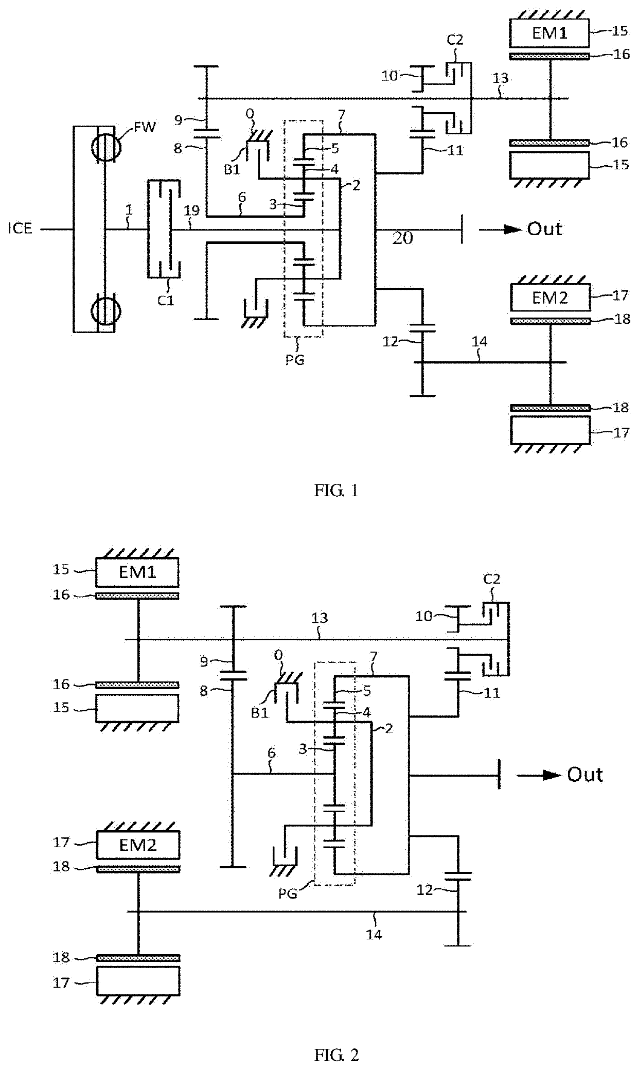
[0058]As shown in FIG. 1, the disclosure provides a hybrid power transmission device including a single planetary gear train PG, an engine, a first transmission mechanism and a second transmission mechanism. Wherein: the single planetary gear train PG includes a sun gear 3, planetary gears 4, a planetary carrier 2 and a gear ring 5, plural planetary gears 4 are circumferentially arranged around and are engaged with the sun gear 3, the gear ring 5 is provided to surround the plural planetary gears 4 and is simultaneously engaged with the plural planetary gears, and the gear ring is directly or indirectly and coaxially connected with an output shaft 20.

[0059]In this example, the first transmission mechanism includes a first electric motor EM1 composed of a first electric motor stator 15, a first electric motor rotor 16 and a first electric motor shaft 13, a first reduction gear pair directly connected to the first electric motor shaft 13, and a second reduction gear pair provided on t...

example 2

[0087]As shown in FIG. 2, this example provides an electric motor drive transmission device including a single planetary gear train PG, a first transmission mechanism and a second transmission mechanism. Wherein: the single planetary gear train PG includes a sun gear 3, planetary gears 4, a planetary carrier 2 and a gear ring 5, plural planetary gears 4 are circumferentially arranged around and are engaged with the sun gear 3, the gear ring 5 is provided to surround the plural planetary gears 4 and is simultaneously engaged with the plural planetary gears, and the gear ring is directly or indirectly and coaxially connected with an output shaft 20.

[0088]In this example, the first transmission mechanism includes a first electric motor EM1 composed of a first electric motor stator 15, a first electric motor rotor 16 and a first electric motor shaft 13, a first reduction gear pair directly connected to the first electric motor shaft 13, and a second reduction gear pair provided on the f...


PUM


Abstract

A transmission device for a power system, comprising a first electric motor (EM1), a second electric motor (EM2), a single planetary gear train (PG), and a reduction gear transmission mechanism. The transmission device is provided with a brake (B1) and two clutches (C1, C2) and is capable of achieving the electric motor driving mode of two gears and satisfying low-speed high-torque and high-speed usage requirements of electric motor driving. During hybrid power driving, an input power splitting and fixed speed ratio mode is adopted to achieve high-efficient operation of the power system. By removing components such as clutches connected to an engine, the transmission device can also be used as a dual-motor two-gear electric motor drive transmission.

Description

RELATED APPLICATIONS[0001]The present application is a National Phase of International Application Number PCT / CN2018 / 081131, filed Mar. 29, 2018, and claims the priority of China Application No. 201720363025.7, filed Mar. 30, 2017.TECHNICAL FIELD[0002]The disclosure relates to a vehicle power transmission technology, in particular to a hybrid power transmission device and an electric motor drive transmission device for a power system based on a single planetary gear train structure, and an operation method thereof.BACKGROUND[0003]As the problems of energy shortage and environmental pollution or the like are more and more serious, various automobile companies are actively committed to the research and development of the automobiles' performance on energy conservation and environmental protection, which mainly focus on the research and development of the internal combustion engine system and the power system, especially the development of new energy power system, so as to effectively ...

Claims


Application Information

Patent Timeline
Patent Type & Authority Patents(United States)
IPC IPC(8): B60K6/445B60K6/365B60K6/387B60K6/54B60K6/26B60K6/38
CPCB60K6/445B60K6/365B60K6/387B60K6/54B60K6/26B60K2006/381B60Y2200/92Y02T10/62B60K1/02B60K6/36B60K6/48B60K2006/4816B60K2006/4808B60K2006/4833
Inventor HAO, YUN
Owner EKONTROL CO LTD
Why Eureka
Try Eureka