Power transmission unit for vehicle

a technology for transmission units and vehicles, applied in machines/engines, transportation and packaging, gearing, etc., can solve the problems of increasing power loss, increasing power loss, and motor rotation inevitably, so as to reduce drag loss and reduce power loss

Active Publication Date: 2010-08-05
TOYOTA JIDOSHA KK
View PDF27 Cites 30 Cited by
  • Summary
  • Abstract
  • Description
  • Claims
  • Application Information

AI Technical Summary

Benefits of technology

[0028]Thus, according to the present invention, the second rotary element of the differential mechanism can be halted by locking the second prime mover by the locking mechanism. In this situation, the torque can be inputted to the first rotary element from the first prime mover, and outputted from the third rotary element to the second speed change gear pair system. Therefore, a predetermined speed change ratio (i.e., a gear stage) can be set by speed change actions of the differential mechanism and the second speed change gear

Problems solved by technology

That is, the motor has to be rotated inevitably when the engine is connected directly to drive the vehicle by the power of the engine.
Therefore, power loss may be incr

Method used


Image

  • Power transmission unit for vehicle
  • Power transmission unit for vehicle
  • Power transmission unit for vehicle

Examples


Embodiment Construction

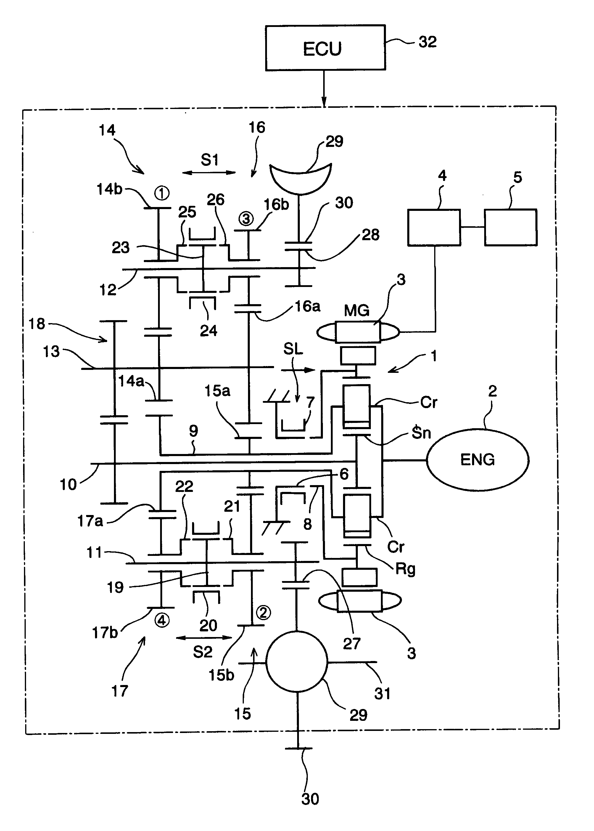
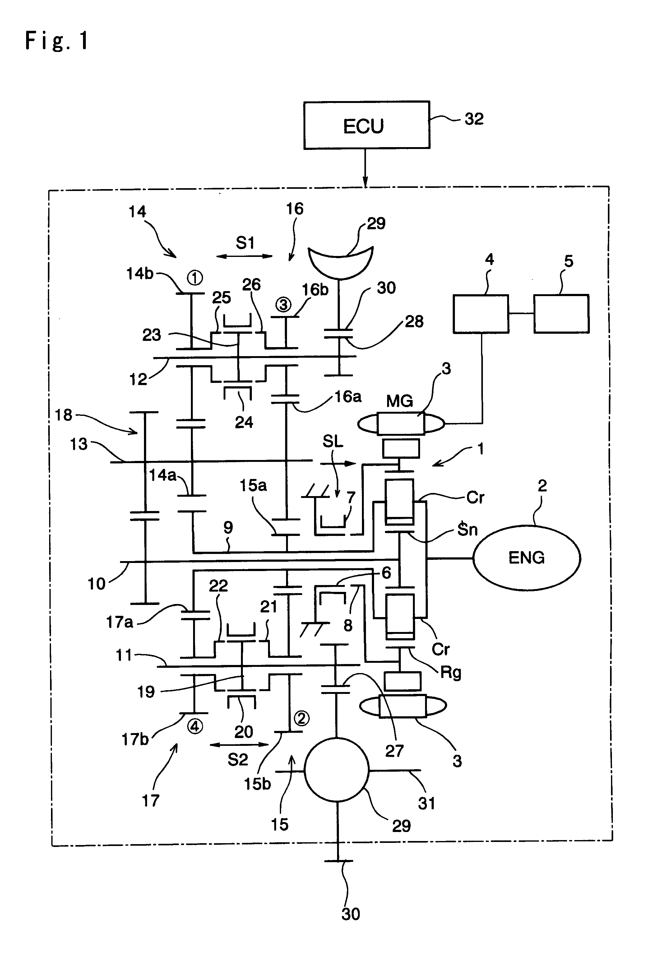
[0052]Next, this invention will be described in connection with its specific examples. A power transmission unit according to the present invention is to be mounted in a vehicle when used. Basically, the power transmission unit is adapted to transmit a power outputted from a first prime mover such as an engine to an output member through a speed change gear pair selected from a plurality of speed change gear pairs each of which has a different gear ratio, and to output the power from the output member. The power transmission unit is also adapted to assist the torque by a second prime mover such as an electric motor or a motor generator according to need, or to output the power from the second prime mover for driving the vehicle. For example, an internal combustion engine such as a gasoline engine, a diesel engine or the like is typically used as the first prime mover, but another kind of power unit e.g., a motor or the like may also be used as the first prime mover.

[0053]On the othe...


PUM


Abstract

A power transmission unit including: a first prime mover; speed change gear pairs; output members; a differential mechanism, which has a first rotary element connected with the first prime mover, a second rotary element, and a third rotary element selectively outputting the power to the output member, and adapted to perform a differential action among those three rotary elements; and a second prime mover connected with the second rotary element. The speed change gear pair includes at lease one pair of first speed change gear pair, arranged between the first rotary element and the output member and allowed to transmit the torque selectively, and at least one pair of second speed change gear pair arranged between the third rotary element and the output member and allowed to transmit the torque selectively. A locking mechanism locks the second prime mover selectively to halt a rotation of the second prime mover.

Description

TECHNICAL FIELD[0001]This invention relates to a power transmission unit for a vehicle adapted to transmit a power outputted from a prime mover such as an engine, an electric motor or the like to an output member such as an output shaft, an output gear or the like. More specifically, the present invention relates to a power transmission unit, which is adapted to vary a ratio between a rotational speed of the prime mover and a rotational speed of the output member by a speed change gear pair.BACKGROUND ART[0002]In order to vary an output torque according to need, or to control the rotational speed of the prime mover to an efficient speed, the power transmission unit of this kind has been used widely in the prior art. Specifically, a mechanism comprising a plurality of gear pairs is used in general to vary the torque and the rotational speed. In case of using the gear pairs to vary the torque and the rotational speed, power transmission efficiency can be improved in comparison with th...

Claims


Application Information

Patent Timeline
IPC IPC(8): F16H3/72B60K6/36B60K6/365B60K6/387B60K6/40B60K6/48B60K6/547B60L50/16B60W10/06B60W10/08B60W10/10B60W20/00F16H37/04F16H59/74F16H61/02F16H63/40F16H63/50
CPCB60K6/365Y02T10/6286B60K6/48B60K6/547B60W10/06B60W10/08B60W10/113B60W10/115B60W20/00F02D29/02F16H3/006F16H3/725F16H37/046F16H2003/0931F16H2061/0422F16H2200/0043F16H2200/0047F16H2200/0052Y02T10/6221Y02T10/6239B60K6/445Y02T10/62B60K6/40B60K17/04F16H59/74B60W20/10
Inventor IDESHIO, YUKIHIKOKOMADA, HIDEAKIOHTA, TAKASHI
Owner TOYOTA JIDOSHA KK
Why Eureka
Try Eureka