Magnetic head for perpendicular recording having a plurality of magnetic path portions

a perpendicular magnetic and recording technology, applied in the direction of magnetic recording, data recording, instruments, etc., can solve the problems of lack of magnetomotive force, erased or attenuated writing, and already written signals on one or more tracks in the neighborhood, so as to reduce the length of the magnetic path

Active Publication Date: 2014-07-29
HEADWAY TECH INC +1
View PDF14 Cites 5 Cited by
  • Summary
  • Abstract
  • Description
  • Claims
  • Application Information

AI Technical Summary

Benefits of technology

[0015]It is an object of the present invention to provide a magnetic head for perpendicular magnetic recording capable of producing a write magnetic field of sufficient magnitude from the main pole while reducing the length of a magnetic path that connects the write shield and the main pole to each other through a yoke layer located on the front side in the direction of travel of a recording medium relative to the main pole.
[0024]In the magnetic head for perpendicular magnetic recording of the present invention, the first coupling part includes the plurality of magnetic path portions, and the coil includes the plurality of winding portions disposed around the plurality of magnetic path portions, respectively. According to the present invention, each of the winding portions can be configured to have a small number of turns so as to achieve a reduction in length of the magnetic path connecting the write shield and the main pole to each other through the first yoke layer. Further, according to the present invention, since the coil includes a plurality of winding portions, the main pole is able to produce a write magnetic field of sufficient magnitude even if each of the winding portions has a small number of turns. Thus, the present invention makes it possible to allow the main pole to produce a write magnetic field of sufficient magnitude while reducing the length of the magnetic path connecting the write shield and the main pole to each other through the yoke layer located on the front side in the direction of travel of the recording medium relative to the main pole.

Problems solved by technology

In particular, in a magnetic disk drive of the perpendicular magnetic recording system which is higher in capability of writing on a recording medium than the longitudinal magnetic recording system, the skew mentioned above can cause the phenomenon that signals already written on one or more tracks in the neighborhood of a track targeted for writing are erased or attenuated during writing of a signal on the track targeted for writing.
However, this would cause a shortage of magnetomotive force produced by the coil, thereby hindering the main pole from producing a write magnetic field of sufficient magnitude.
As such, it has conventionally been difficult to allow the main pole to produce a write magnetic field of sufficient magnitude while reducing the length of a magnetic path that connects the write shield and the main pole to each other through a yoke layer located on the front side in the direction of travel of the recording medium (i.e., the trailing side) relative to the main pole.

Method used


Image

  • Magnetic head for perpendicular recording having a plurality of magnetic path portions
  • Magnetic head for perpendicular recording having a plurality of magnetic path portions
  • Magnetic head for perpendicular recording having a plurality of magnetic path portions

Examples


first embodiment

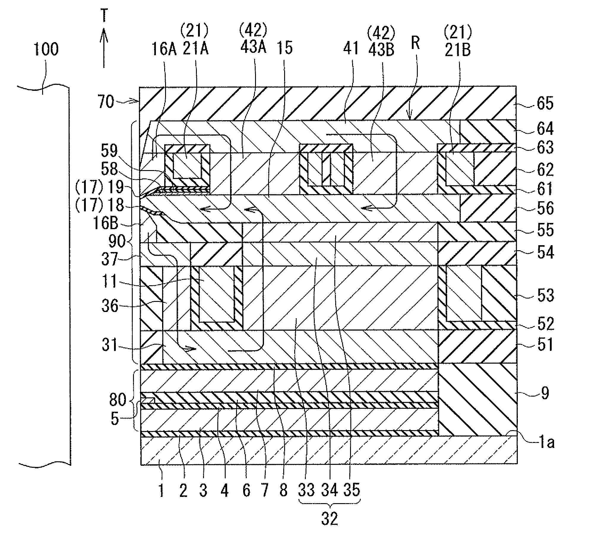
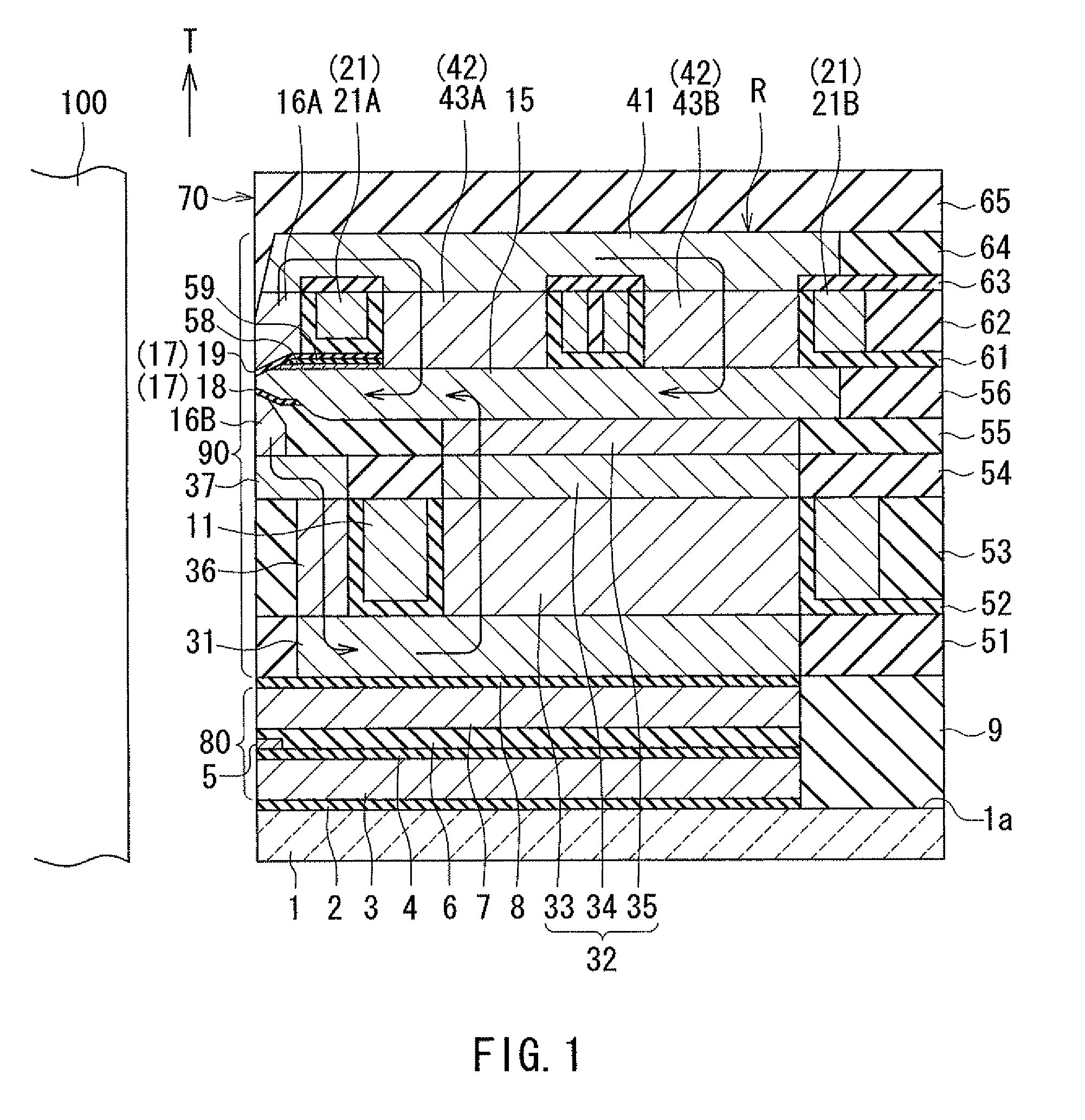
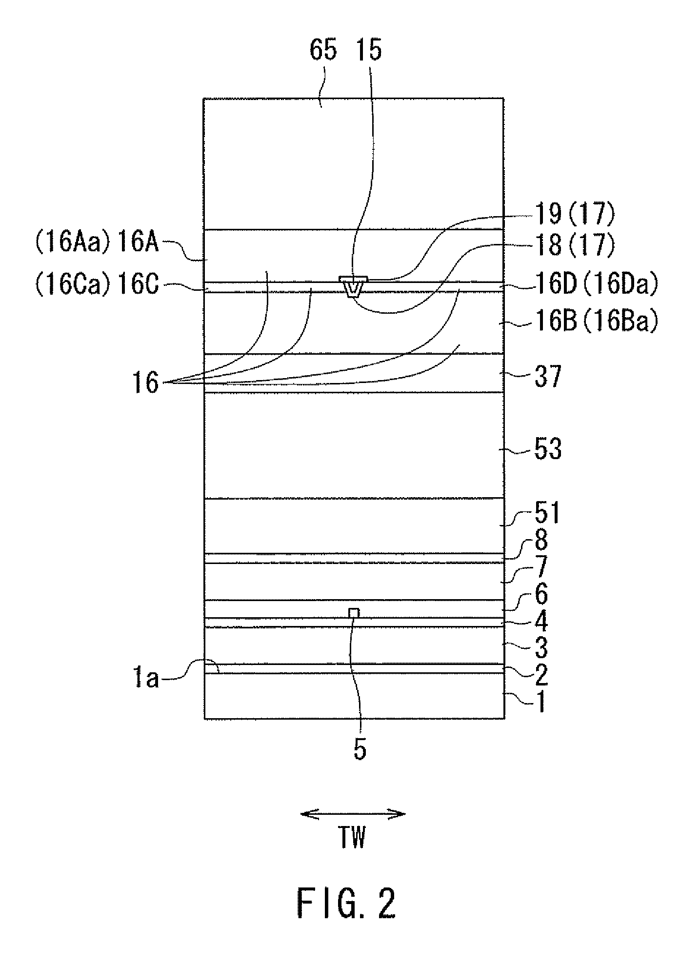
[0043]Preferred embodiments of the present invention will now be described in detail with reference to the drawings. First, reference is made to FIG. 1 to FIG. 4 to describe the configuration of a magnetic head according to a first embodiment of the invention. FIG. 1 is a cross-sectional view showing the magnetic head according to the present embodiment. The arrow with the symbol T in FIG. 1 indicates the direction of travel of a recording medium. The arrows drawn within the magnetic head in FIG. 1 indicate the flows of magnetic flux. FIG. 2 is a front view showing the medium facing surface of the magnetic head according to the present embodiment. FIG. 3 is a plan view showing a second portion of a coil of the magnetic head according to the present embodiment. FIG. 4 is a plan view showing a first portion of the coil of the magnetic head according to the present embodiment. In each of FIG. 2 to FIG. 4, the arrow with the symbol TW indicates the track width direction. In each of FIG....

second embodiment

[0097]A magnetic head according to a second embodiment of the invention will now be described with reference to FIG. 5. FIG. 5 is a plan view showing a first portion of the coil of the magnetic head according to the present embodiment. The magnetic head according to the present embodiment is different from the magnetic head according to the first embodiment in the following ways. The magnetic head according to the present embodiment has a lead layer 125 in place of the lead layers 25 and 26 of the first embodiment. The lead layer 125 is made of a conductive material such as copper.

[0098]Further, in the present embodiment, the coil includes a first portion 121 in place of the first portion 21 of the first embodiment. The positional relationship of the first portion 121 with the main pole 15, the write shield 16 and the return path section R is the same as that of the first portion 21 of the first embodiment. The plurality of magnetic path portions 43 of the return path section R sepa...

third embodiment

[0104]A magnetic head according to a third embodiment of the invention will now be described with reference to FIG. 6 to FIG. 8. FIG. 6 is a cross-sectional view showing the magnetic head according to the present embodiment. FIG. 7 is a plan view showing a second portion of the coil of the magnetic head according to the present embodiment. FIG. 8 is a plan view showing a first portion of the coil of the magnetic head according to the present embodiment. Note that a portion of the view of FIG. 6 closer to the substrate 1 relative to the main pole 15 shows a cross section taken at the position indicated by line 6-6 of FIG. 7, and the remaining portion of the view of FIG. 6 shows a cross section taken at the position indicated by line 6-6 of FIG. 8.

[0105]The magnetic head according to the present embodiment is different from the magnetic head according to the first embodiment in the following ways. In the magnetic head according to the present embodiment, the main pole 15 includes not ...


PUM

PropertyMeasurementUnit
thicknessaaaaaaaaaa
thicknessaaaaaaaaaa
angleaaaaaaaaaa

Abstract

A magnetic head includes a coil, a main pole, a write shield, and a return path section. The return path section includes a yoke layer located on the front side in the direction of travel of a recording medium relative to the main pole, and a coupling part coupling the main pole and the yoke layer to each other. The coupling part includes a plurality of magnetic path portions that separate a magnetic flux into a plurality of fluxes and allow the fluxes to pass therethrough in parallel. The coil includes a plurality of winding portions disposed around the plurality of magnetic path portions, respectively.

Description

BACKGROUND OF THE INVENTION[0001]1. Field of the Invention[0002]The present invention relates to a magnetic head for perpendicular magnetic recording that is used for writing data on a recording medium by means of a perpendicular magnetic recording system, and more specifically, to a magnetic head for perpendicular magnetic recording that has a main pole and a shield.[0003]2. Description of the Related Art[0004]The recording systems of magnetic read / write apparatuses include a longitudinal magnetic recording system wherein signals are magnetized in a direction along the plane of a recording medium (the longitudinal direction) and a perpendicular magnetic recording system wherein signals are magnetized in a direction perpendicular to the plane of a recording medium. It is known that the perpendicular magnetic recording system is harder to be affected by thermal fluctuation of the recording medium and capable of providing higher linear recording density, compared with the longitudinal...

Claims


Application Information

Patent Timeline
Patent Type & Authority Patents(United States)
IPC IPC(8): G11B5/17G11B5/127G11B5/31
CPCG11B5/1278G11B5/3123G11B5/315
Inventor SASAKI, YOSHITAKAITO, HIROYUKISATO, KAZUKITANEMURA, SHIGEKIARAKI, HIRONORISHIMIZU, TATSUYA
Owner HEADWAY TECH INC
Why Eureka
Try Eureka