
Device case and mounting apparatus

a technology of flexible support and device case, which is applied in the direction of electric apparatus casing/cabinet/drawer, details of portable computers, instruments, etc., can solve the problems of difficult placement in an appropriate position, environmental and impact sensitive nature, and modern portable electronic devices such as tablet computing devices, which are not well adapted to be positioned other than on a flat surfa

Inactive Publication Date: 2014-08-12
VITEC HLDG ITAL SRL
View PDF17 Cites 55 Cited by
  • Summary
  • Abstract
  • Description
  • Claims
  • Application Information

AI Technical Summary

Benefits of technology

The patent text describes a multi-function case for a tablet computer that can be adjusted to support the tablet in different configurations. The case can protect the tablet from rough contact and wear. The case is also designed to allow for rotation of the tablet from portrait to landscape orientation. The technical effect of the text is to provide a versatile and protective solution for using tablets in various settings.

Problems solved by technology

Modern portable electronic devices, such as tablet computing devices, are not well adapted to be positioned other than on a flat surface, with the screen facing directly vertically.
These items are typically flat, rectangular objects which may be difficult to place in an appropriate position for hands-free use while viewing.
They may also be of a somewhat environmentally and impact sensitive nature.

Method used


Image

  • Device case and mounting apparatus
  • Device case and mounting apparatus
  • Device case and mounting apparatus

Examples


first embodiment

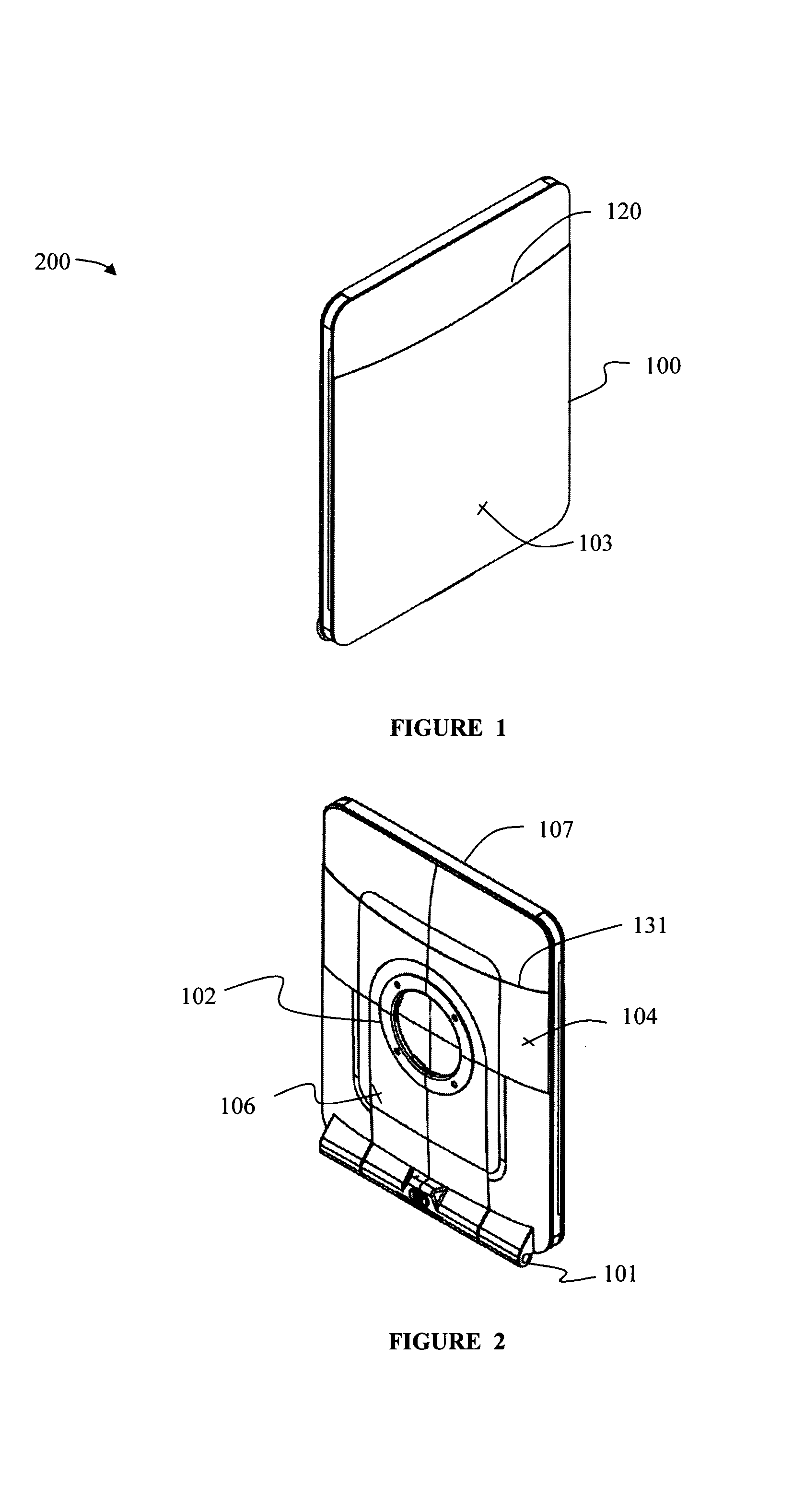
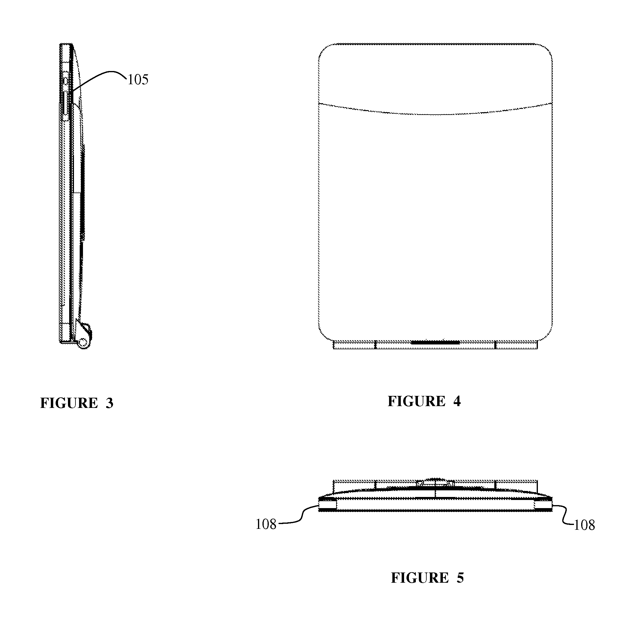
[0035]FIGS. 1-5 illustrate the stowed configuration 200 of case and support assembly 100 according to the present invention. In some embodiments, the electronic device is a tablet computing device. The electronic device may also be another device. The electronic device 110 may have a screen 111.

[0036]In some embodiments, the case and support assembly 100 is adapted to be a protective cover as well as a support for viewing the electronic device, which may be a tablet, in a variety of positions. When in the stowed configuration 200, the case and support assembly may still allow access to aspects of the device via slots or openings in the rim 105, which may be used to operate the device, or for other reasons.

[0037]As seen in FIG. 2, a rear section 104 covers over portions of the rear of the case and support assembly 100. The rear section 104 may be adapted to fit around a rear support 106, which is the bridge between the main hinge 101 and the rotary joint 102. The rear section 104 is ...

second embodiment

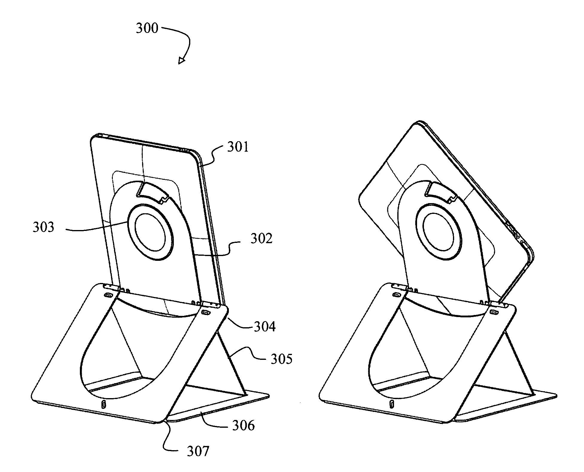
[0047]In the present invention, as seen in FIG. 19, a case and support assembly may use another configuration. In this embodiment, a portion of one layer of the device case folds away from the panel in which it sometimes resides in order to form a support. The fold away portion may be inserted into slots on the adjoining panel to form a stable base as shown.

[0048]In some embodiments, a front section may have an outer front section 306 and an inner section 305. The outer front section 306 and inner front section 305 may form a single front section which acts as a front cover for an electronic device when the case and support assembly are in a stowed configuration. When in an open configuration, the inner front section may snap out of the outer front section allowing the inner front section to interlock with the outer rear section 304, forming a base of a support structure. As illustrated in FIG. 19 in a deployed configuration, the case is used as a support structure which may hold th...


PUM

PropertyMeasurementUnit
flexibleaaaaaaaaaa
impact sensitiveaaaaaaaaaa
rotationaaaaaaaaaa

Abstract

A multi-function case and support for an electronic device, such as a tablet computer. The case may be adapted to support the tablet in a variety of configurations, such as similar to a laptop computer configuration, and as a raised support. The case may also protect the electronic device from rough contact and other wear. In the raised support configuration, the case and support may be adapted to allow for rotation of the tablet from a landscape to a portrait attitude.

Description

CROSS-REFERENCE TO RELATED APPLICATIONS[0001]This application claims priority to U.S. Provisional Patent Application No. 61 / 366,940 to Hale, filed Jul. 23, 2010, which is hereby incorporated by reference in its entirety. This application claims priority to U.S. Provisional Patent Application No. 61 / 422,124 to Hale, filed Dec. 10, 2010, which is hereby incorporated by reference in its entirety.BACKGROUND[0002]1. Field of the Invention[0003]The present invention relates to a device case and a flexible support apparatus, adapted to support an item mounted in the device case in a variety of configurations.[0004]2. Description of Related Art[0005]Modern portable electronic devices, such as tablet computing devices, are not well adapted to be positioned other than on a flat surface, with the screen facing directly vertically. These items are typically flat, rectangular objects which may be difficult to place in an appropriate position for hands-free use while viewing. They may also be of ...

Claims


Application Information

Patent Timeline
Patent Type & Authority Patents(United States)
IPC IPC(8): B65D85/00
CPCG06F1/166A45C2011/003A45C2200/15F16M11/041F16M11/10F16M13/00G06F1/1628H05K5/0226B32B15/085B32B2250/03H05K5/0234
Inventor HALE, ERIC, C.
Owner VITEC HLDG ITAL SRL
Learn More