
Rod to rod cross connector

a cross-connector and rod-to-rod technology, applied in the field of systems for stabilizing and fixing the spine, can solve the problem of small footprint after, and achieve the effect of reducing the transverse width of the assembly and small footprin

Inactive Publication Date: 2014-09-09
AESCULAP IMPLANT SYST
View PDF397 Cites 47 Cited by
  • Summary
  • Abstract
  • Description
  • Claims
  • Application Information

AI Technical Summary

Benefits of technology

The present invention provides rod to rod cross connectors that overcome the drawbacks of conventional connectors. These connectors have a central body and one or more actuators that can pivot the levers into a closed position. When the levers are closed, they reduce the transverse width of the assembly, resulting in a smaller footprint after implantation. The technical effects of this invention are a more compact and efficient rod to rod cross connector for use in spine surgeries.

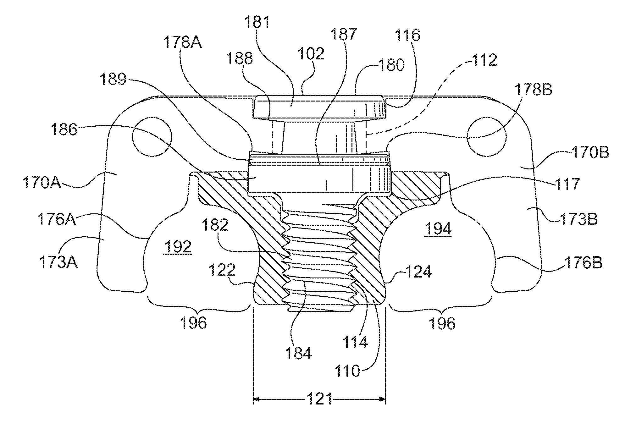
Problems solved by technology

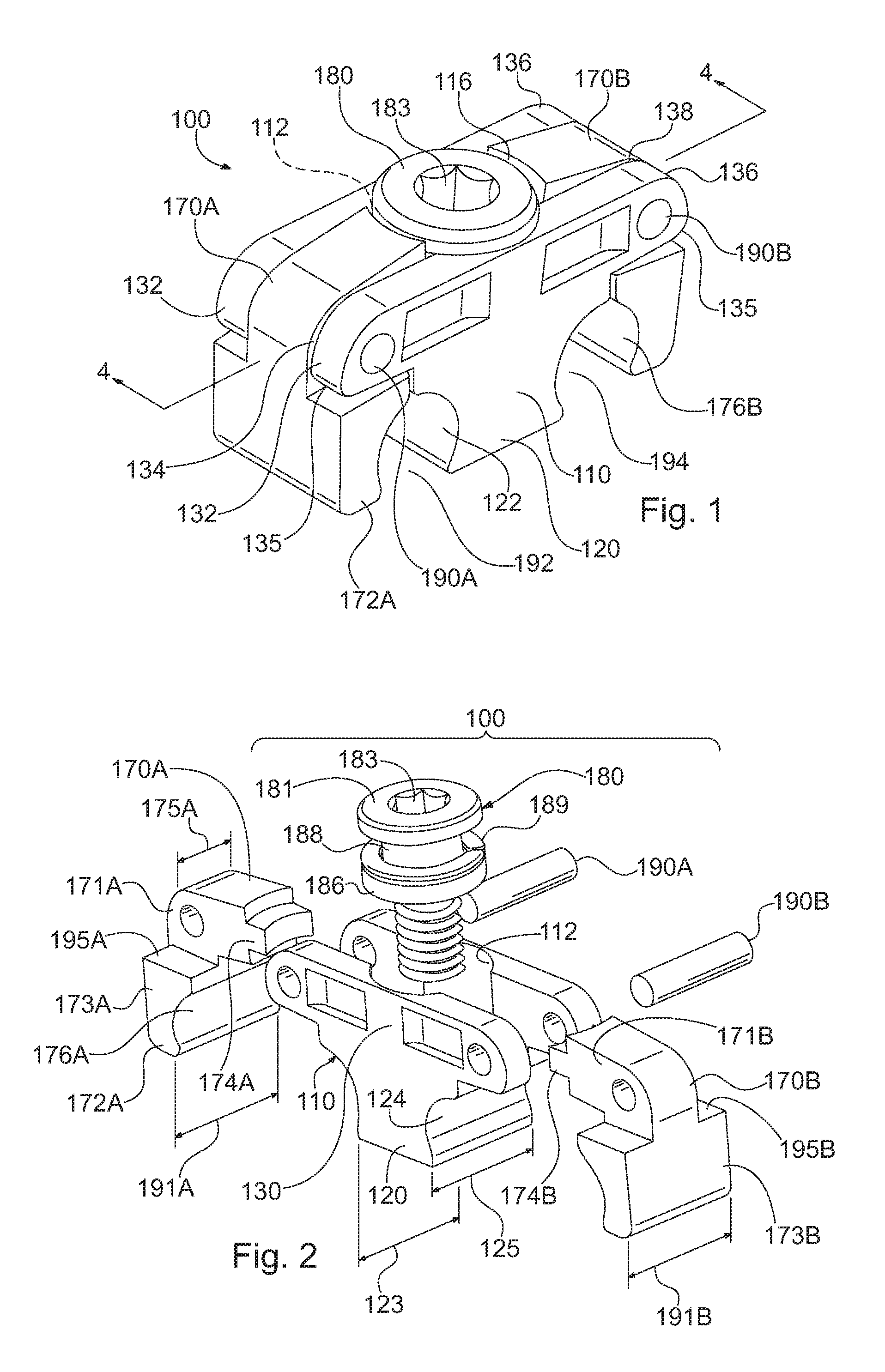
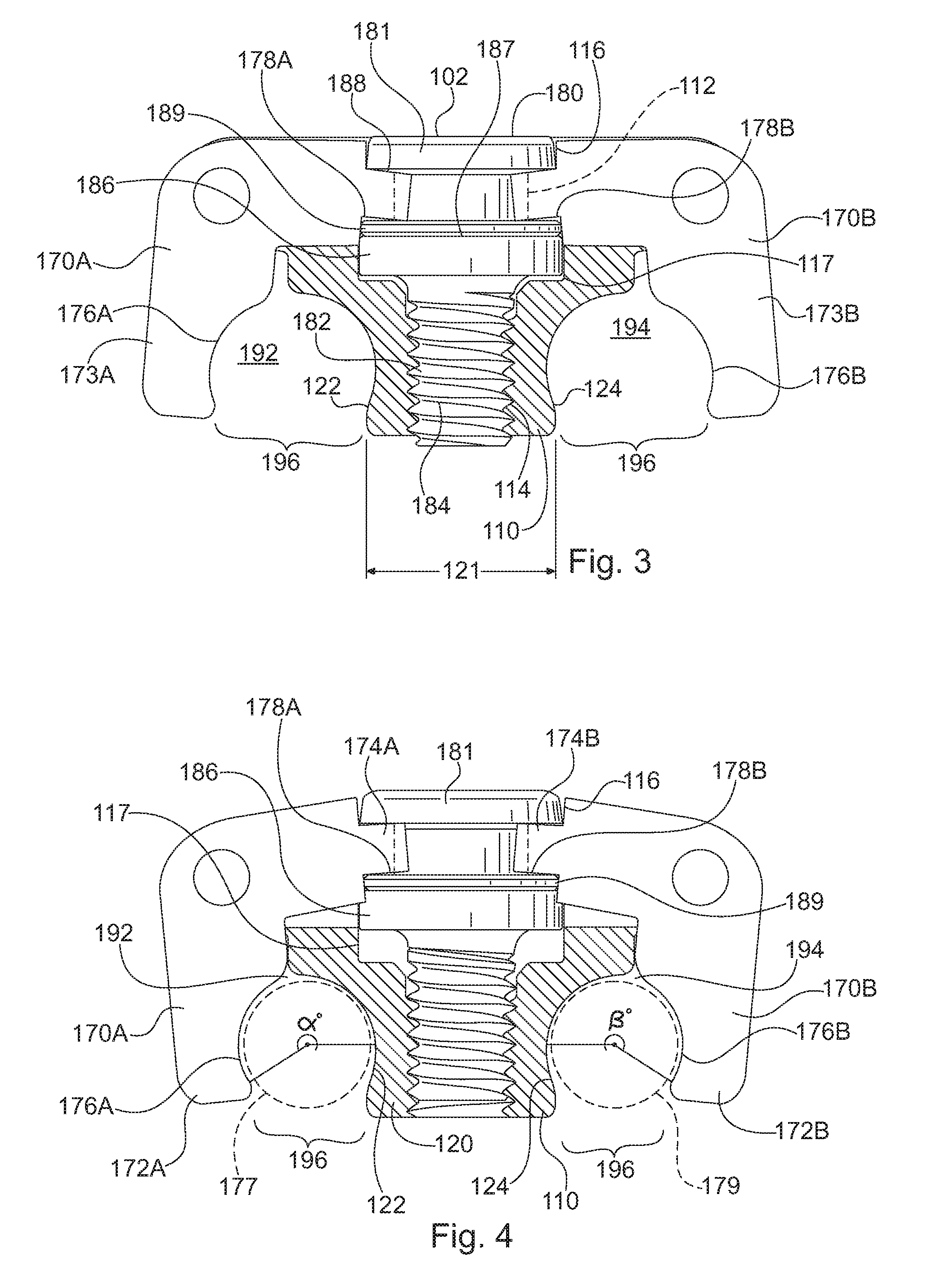
Drawing the first and second levers toward one another reduces the transverse width of the assembly, resulting in a smaller footprint after it is implanted.

Method used


Image

  • Rod to rod cross connector
  • Rod to rod cross connector
  • Rod to rod cross connector

Examples


Embodiment Construction

[0013]The term “axial”, as used herein, means a direction parallel to the longitudinal axis defining a rod receiving channel in a rod to rod connector. For example, dimensions 191A and 191B in FIG. 2 extend in the axial direction and are referred to as axial widths. The long dimensions of pins 190A and 190B in FIG. 1 are also examples of dimensions extending in the axial direction relative to rod to rod connector 100.

[0014]The term “transverse”, as used herein, means a direction perpendicular to the axial direction and parallel to a plane passing through the longitudinal axes of both rod channels. For example, dimension 121 in FIG. 3 extends in the transverse direction and is referred to herein as a transverse width.

[0015]Rod to rod cross connectors in accordance with the invention feature a central body and one or more clamping mechanisms that apply forces on rods to be connected. The clamping mechanism(s) apply forces on each rod in a direction toward the central body, so as to pu...


PUM


Abstract

A cross connector for connecting elongated fixation elements, such as spinal fixation rods, includes a central body and one or more actuators. The rod to rod connector may include a first lever and a second lever coupled to the central body. The first lever may include a free end separated from the central body by a first channel. The second lever may include a free end separated from the central body by a second channel. The one or more actuators may be operable to pivot the first and second levers into a relatively closed position. When the first and second levers are in the relatively closed position, the free ends of the first and second levers are moved toward one another and toward the central body to contract the first and second channels.

Description

FIELD[0001]The present invention relates generally to systems for stabilization and fixation the spine, and more particularly to an assembly for rigidly connecting two spinal rods together using one or more actuators in an arrangement that distributes clamping forces uniformly to the rods, and minimizes the transverse width of the assembly.BACKGROUND[0002]When performing a lateral or anterolateral corpectomy, the diseased or damaged vertebral body and adjacent disc are removed. Removal of the vertebral body and disc leaves a void in the spinal column. Therefore, a vertebral body replacement (VBR) device is placed into the void to provide support to the spinal column. Although the VBR device provides support, the spinal column can still be unstable, particularly in torsion or bending maneuvers. Therefore, surgeons often place a dual rod construct or other stabilization system over the affected level to provide additional stability. In a dual rod construct, pedicle screws are placed i...

Claims


Application Information

Patent Timeline
Patent Type & Authority Patents(United States)
IPC IPC(8): A61B17/70
CPCA61B17/7049
Inventor BUSS, DONALD A.HASKINS, TYLER
Owner AESCULAP IMPLANT SYST
Learn More