Image forming apparatus

a technology of image forming apparatus and forming tube, which is applied in the direction of electrographic process apparatus, instruments, optics, etc., can solve the problems of formation of abnormal image called toner scattering, formation of gap between thick paper and transfer belt, formation of above-described abnormal image, etc., to achieve excellent image formation and suppress the disorder of toner imag

Active Publication Date: 2014-09-16
KONICA MINOLTA BUSINESS TECH INC
View PDF15 Cites 0 Cited by
  • Summary
  • Abstract
  • Description
  • Claims
  • Application Information

AI Technical Summary

Benefits of technology

[0012]It is, therefore, a main object of the present invention to provide an image forming apparatus that can suppress the disorder of a toner image and can form excellent images.
[0015]Preferably, in the image forming apparatus, the belt movement restricting section includes a fixing member having a cross-sectional shape that allows the fixing member to withstand a push given by the transfer belt when the fixing member comes in contact with the transfer belt.

Problems solved by technology

This causes disorder of the toner image, leading to formation of an abnormal image called toner scattering.
The transfer belt inwardly deflects due to the shock of such hitting, resulting in formation of a gap between the thick paper and the transfer belt.
Electrical discharge may occur across the gap, leading to formation of the above-described abnormal image.
Unfortunately, in the image forming apparatus disclosed in JP-A-2010-139603, the thick paper still hits the transfer belt even though the shock is reduced, and thus the transfer belt still deflects inwardly and a gap is formed, resulting in occurrence of electrical discharge across the gap in some cases.
In addition, if the position of the transfer belt varies, the area of paper pre-nipped between the transfer belt and the secondary transfer roller is different between before and after the variation, which may cause color or density change in the formed image.

Method used


Image

  • Image forming apparatus
  • Image forming apparatus
  • Image forming apparatus

Examples


first embodiment

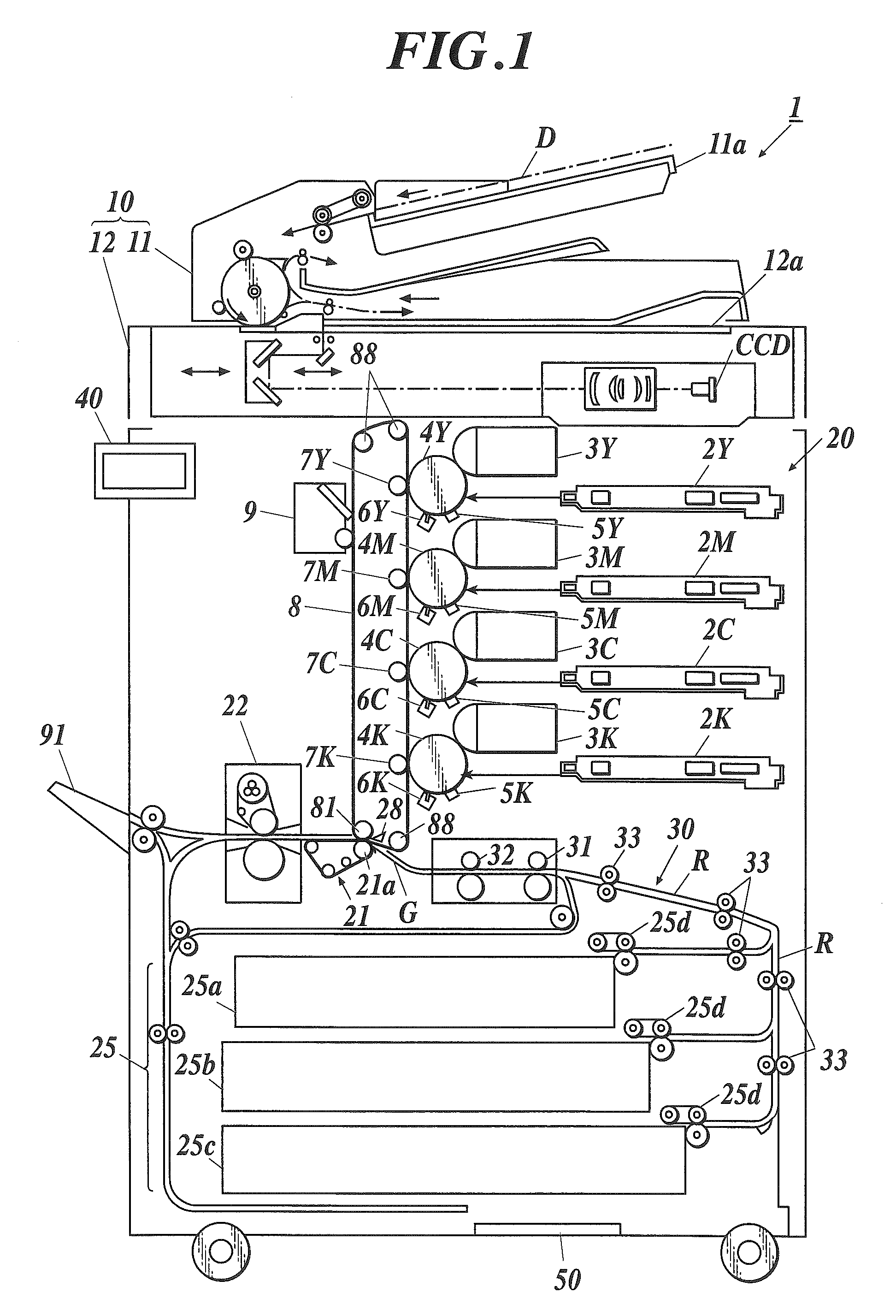
[0033]FIG. 1 is a schematic structural diagram illustrating an image forming apparatus 1.

[0034]The image forming apparatus 1 has a copying function of reading an image from a document, forming an image on paper P on the basis of the read image data, and outputting the image; and a printing function of receiving page data containing image data and job data containing image forming conditions for each image data from external devices, forming an image on the paper P on the basis of the received page data and job data, and outputting the image.

[0035]As shown in FIG. 1, the image forming apparatus 1 includes an image reading unit 10, an image forming unit 20, a paper housing 25, a conveyance unit 30, an operational unit 40, and a controller 50.

[0036]The image reading unit 10 includes a document feeding section 11 called an automatic document feeder (ADF), and a reading section 12.

[0037]The reading section 12 reads an image on a document D placed on a contact glass 12a as a reading place...

second embodiment

[0089]A second embodiment of the image forming apparatus according to the present invention is now described. The configurations similar to those in the first embodiment are designated by the same numerals and overlapping description is omitted.

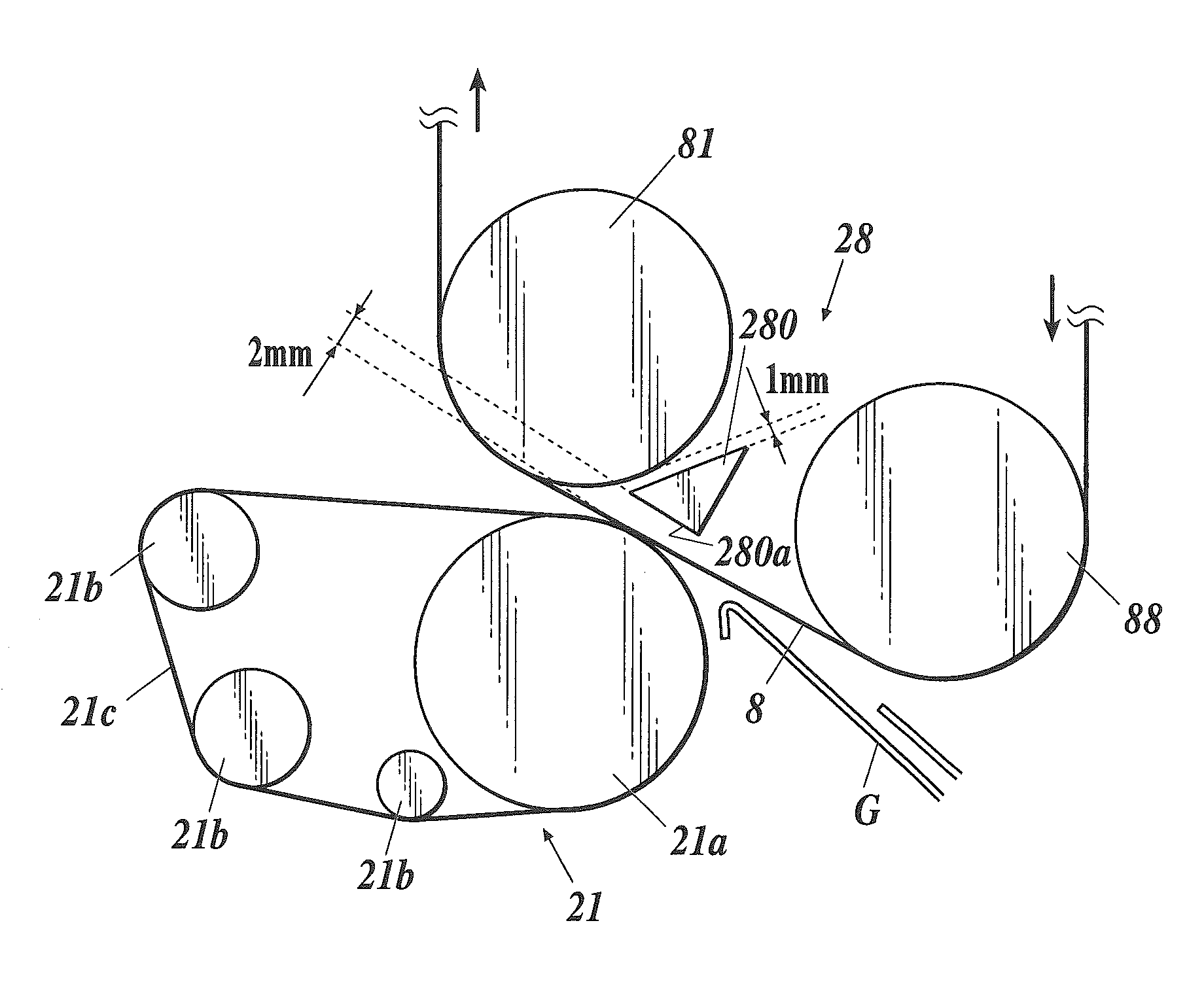
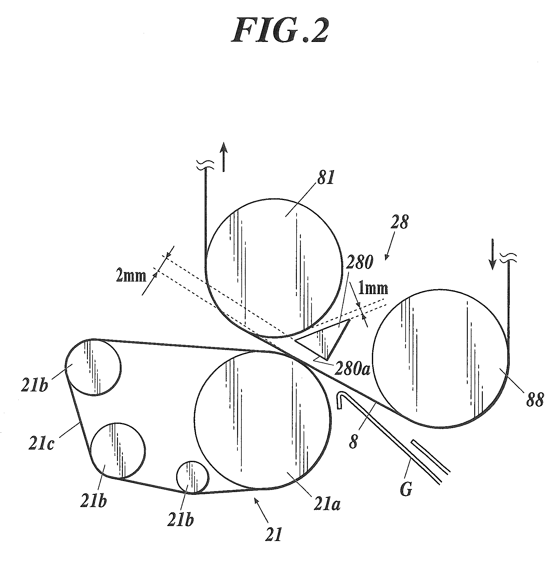
[0090]As shown in FIGS. 6 and 7, rollers 281 (belt movement restricting roller) of a belt movement restricting section 28 are provided between a backup roller 81 and a tension roller 88 upstream from the backup roller 81 in the vicinity of the back of a transfer belt 8. A plurality of (three in this embodiment) rollers 281 hold the transfer belt 8 to restrict a movement of the transfer belt 8 toward the backup roller 81 when the transfer belt 8 is pushed by the paper P during secondary transfer. The rollers 281 are separated from the transfer belt 8 with a predetermined amount of space therebetween when a secondary transfer is not performed.

[0091]The rollers 281 each composed of, for example, a stainless steel roller having a diameter of 6 mm...

third embodiment

[0101]A third embodiment of the image forming apparatus according to the present invention is now described. The configurations similar to those in the first and second embodiments are designated by the same numerals and overlapping description is omitted.

[0102]As shown in FIGS. 8 and 9, rollers 281 and a belt 282 of a belt movement restricting section 28 are provided between a backup roller 81 and a tension roller 88 upstream from the backup roller 81 in the vicinity of the back of a transfer belt 8.

[0103]The rollers 281 each composed of, for example, a stainless steel roller having a diameter of 6 mm, and are each rotatably supported by an undepicted support.

[0104]The belt 282 is an endless belt rotatably stretched over the two rollers 281, and is formed, for example, by molding of an insulating resin material.

[0105]The belt movement restricting section 28 including the belt 282 stretched over the two rollers 281 holds the transfer belt 8 to restrict a movement of the transfer bel...


PUM


Abstract

An image forming apparatus includes a transfer belt, a pressure receiving roller, a secondary transfer roller, and a belt movement restricting section. The belt movement restricting section is disposed close to the back of the belt. When pressing the belt between the pressure receiving roller and the secondary transfer roller, and nipping paper between the belt and the secondary transfer roller, an angle defined by the portion, upstream from the secondary transfer roller, of the belt and an imaginary line connecting the pressure-receiving-roller axis with the secondary-transfer-roller axis is less than 90 degrees. During non-secondary-transfer mode, the belt movement restricting section is separated from the belt. During secondary transfer, the belt movement restricting section holds the belt not to let the belt pushed by the paper move toward the pressure receiving roller.

Description

BACKGROUND OF THE INVENTION[0001]1. Field of the Invention[0002]The present invention relates to an image forming apparatus.[0003]2. Description of Related Art[0004]Typical image forming apparatuses form an image on paper by performing primarily transfer of a toner image to a surface of an endless transfer belt, which is rotatably stretched over a plurality of rollers including a drive roller, a driven roller, and a backup roller, from a photoreceptor drum (an image carrier), and then performing secondary transfer of the toner image to the paper.[0005]Such image forming apparatuses have a secondary transfer roller that presses the transfer belt against the backup roller. When a portion of the transfer belt on which a toner image has been primarily transferred passes through the backup roller, paper is allowed to pass between the transfer belt and the secondary transfer roller, so that the toner image is secondarily transferred on the paper.[0006]In such image forming apparatuses, el...

Claims


Application Information

Patent Timeline
Patent Type & Authority Patents(United States)
IPC IPC(8): G03G15/01
CPCG03G15/161G03G15/168
Inventor NISHIDA, SATOSHIYAMAKI, HIDEONISHISAKA, YUSUKE
Owner KONICA MINOLTA BUSINESS TECH INC
Why Eureka
Try Eureka