Image forming apparatus with support belt deforming member

a technology of support belt and support belt, which is applied in the direction of electrographic process apparatus, instruments, optics, etc., can solve the problems of formation of abnormal images called toner scattering, formation of gap between thick paper and transfer belt, formation of abnormal images, etc., to achieve excellent images and suppress the disorder of toner images

Active Publication Date: 2014-09-30
KONICA MINOLTA BUSINESS TECH INC
View PDF15 Cites 0 Cited by
  • Summary
  • Abstract
  • Description
  • Claims
  • Application Information

AI Technical Summary

Benefits of technology

[0013]It is, therefore, a main object of the present invention to provide an image forming apparatus that can suppress the disorder of a toner image and can form excellent images.

Problems solved by technology

This causes disorder of the toner image, leading to formation of an abnormal image called toner scattering.
The transfer belt inwardly deflects due to the shock of such hitting, resulting in formation of a gap between the thick paper and the transfer belt.
Electrical discharge may occur across the gap, leading to formation of the above-described abnormal image.
Unfortunately, in the image forming apparatus disclosed in JP-A-2010-72311, paper which is to be nipped for a transfer is conveyed in a direction substantially perpendicular to a line that connects the axis of the secondary transfer roller with the axis of a counter roller.
Thus, the technology is not intended to be a measure against a load on the transfer belt in the vicinity of the secondary transfer roller.

Method used


Image

  • Image forming apparatus with support belt deforming member
  • Image forming apparatus with support belt deforming member
  • Image forming apparatus with support belt deforming member

Examples


first embodiment

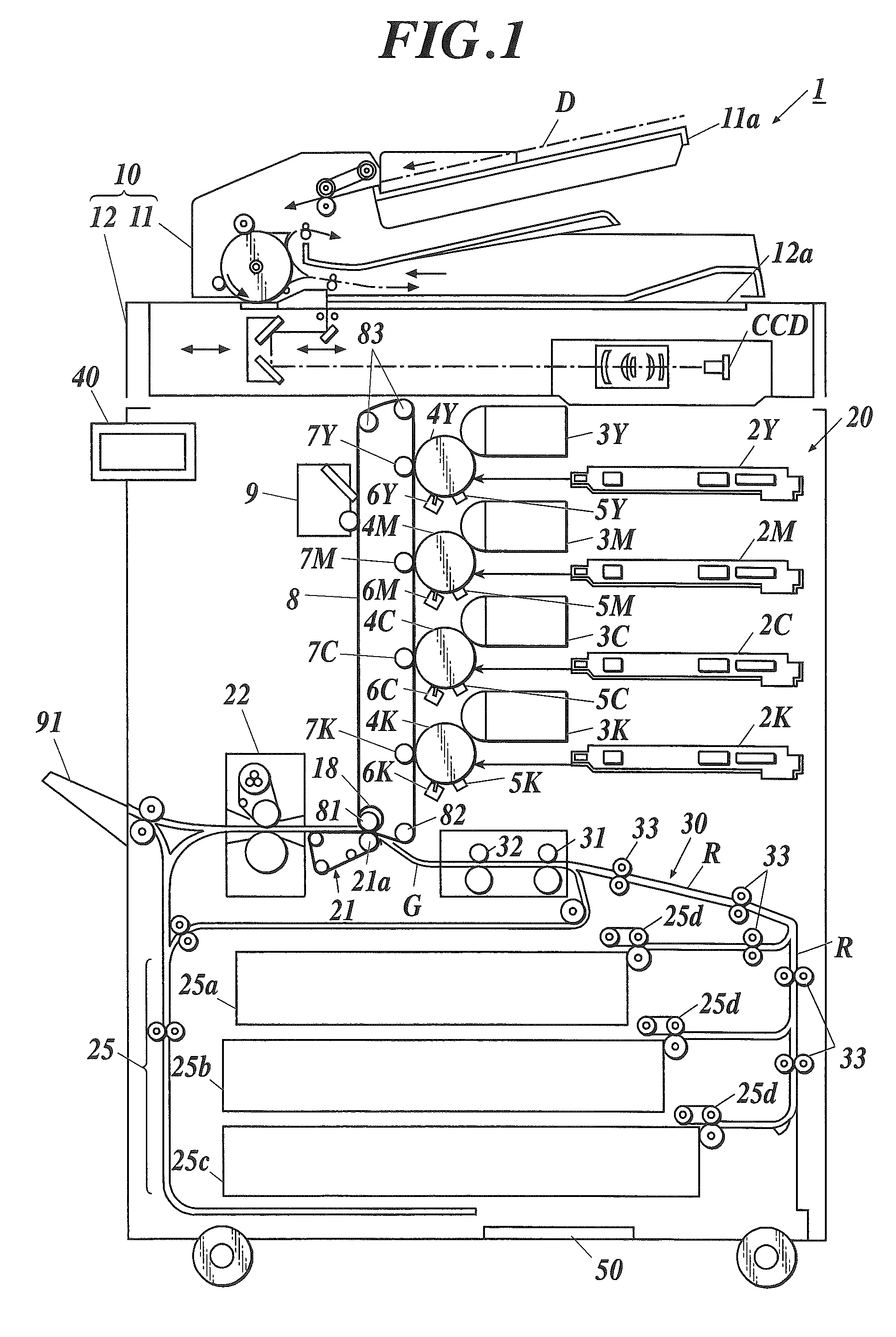
[0033]FIG. 1 is a schematic structural diagram illustrating an image forming apparatus 1.

[0034]The image forming apparatus 1 has a copying function of reading an image from a document, forming an image on paper P on the basis of the read image data, and outputting the image; and a printing function of receiving page data containing image data and job data containing image forming conditions for each image data from external devices, forming an image on the paper P on the basis of the received page data and job data, and outputting the image.

[0035]As shown in FIG. 1, the image forming apparatus 1 includes an image reading unit 10, an image forming unit 20, a paper housing 25, a conveyance unit 30, an operational unit 40, and a controller 50.

[0036]The image reading unit 10 includes a document feeding section 11 called an automatic document feeder (ADF), and a reading section 12.

[0037]The reading section 12 reads an image on a document D placed on a contact glass 12a as a reading place...

second embodiment

[0110]A second embodiment of the image forming apparatus according to the present invention is now described. The configurations similar to those in the first embodiment are designated by the same numerals and their overlapping description is omitted.

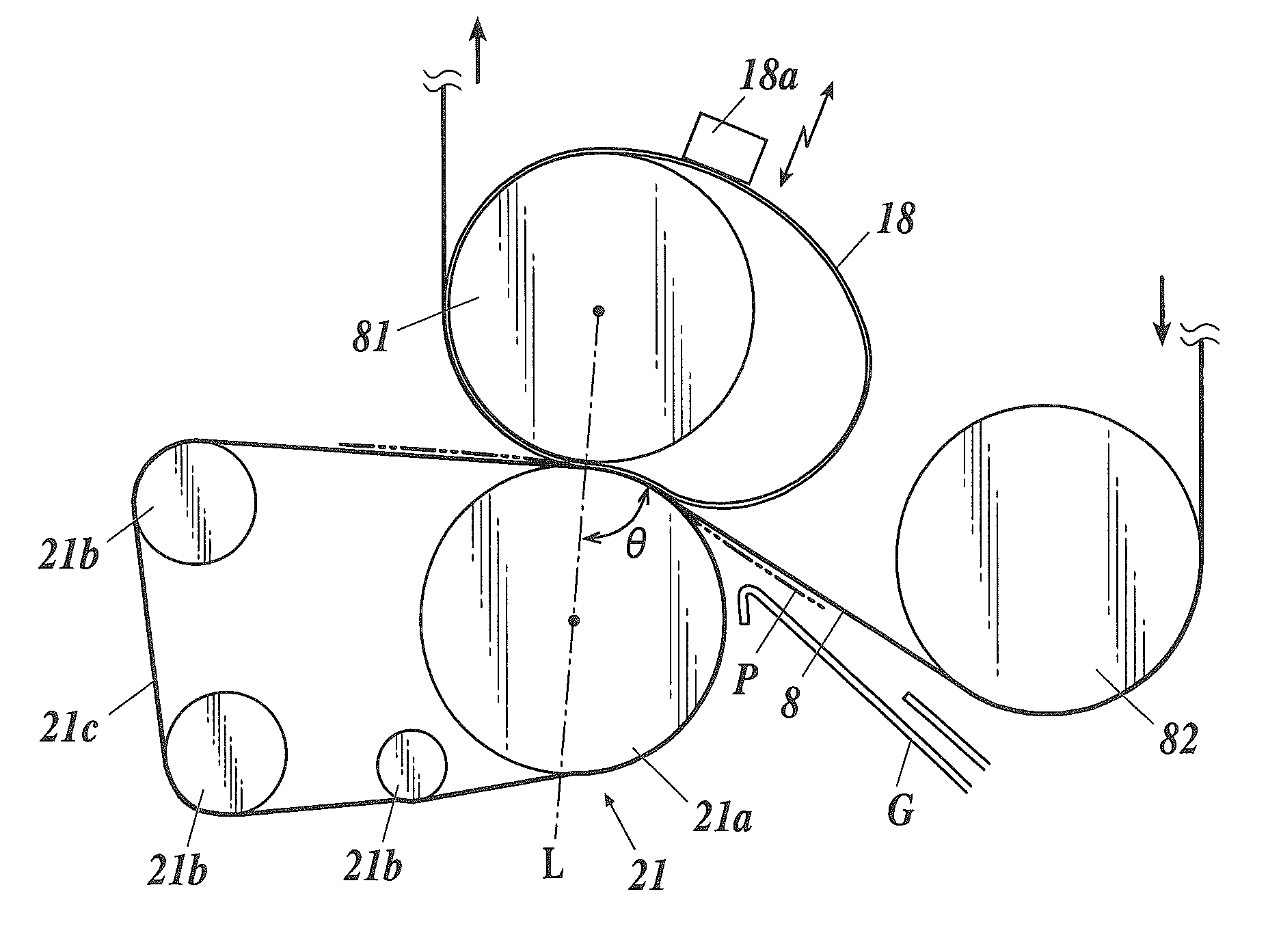
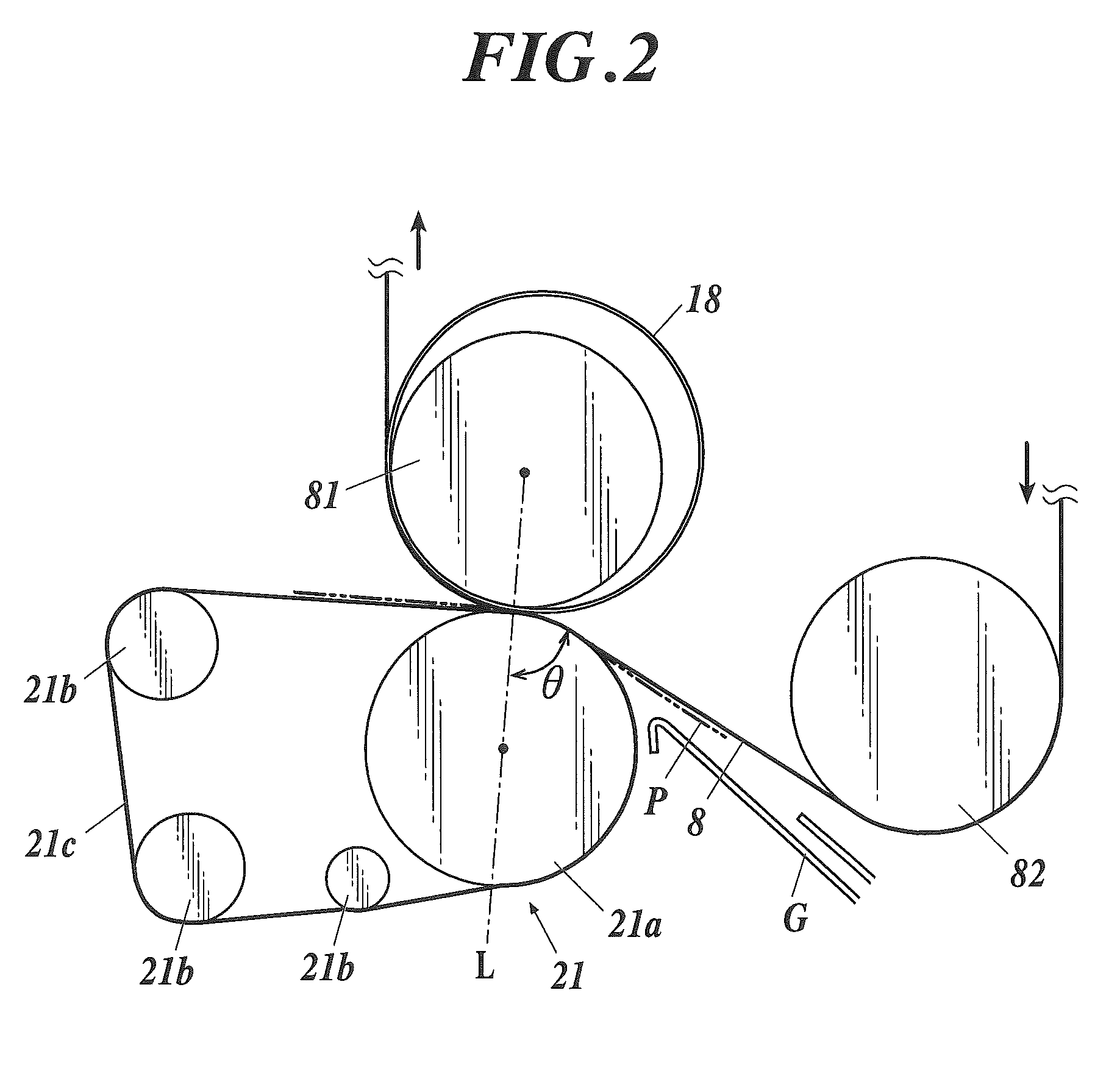
[0111]In the image forming apparatus 1, an endless support belt is stretched over at least one of a backup roller 81 and a suspension roller 82, over which a transfer belt 8 is stretched, in the vicinity of the back of the transfer belt 8.

[0112]In the second embodiment, as shown in FIG. 8, a support belt 28 is stretched over the suspension roller 82, and part of the support belt 28 around the suspension roller 82 is held between the suspension roller 82 and the transfer belt 8.

[0113]The support belt 28 is, for example, an elastic tubular member having a Young's modulus of, for example, about 3 to about 7 MPa / mm2 composed of conductive resin such as polyimide (PI), polyamide-imide (PAI), polycarbonate (PC), and polyphenylene sulfide (PPS...

third embodiment

[0140]A third embodiment of the image forming apparatus according to the present invention is now described. The configurations similar to those in the first embodiment are designated by the same numerals and overlapping description is omitted.

[0141]The image forming apparatus 1 has an endless support belt stretched over both a backup roller 81 and a suspension roller 82, over which a transfer belt 8 is stretched, in the vicinity of the back of the transfer belt 8.

[0142]As shown in FIG. 11, a support belt 88 of the third embodiment is stretched over both the backup roller 81 and the suspension roller 82, and part of the support belt 88 around both the backup roller 81 and the suspension roller 82 is held between the backup roller 81 and the transfer belt 8 and between the suspension roller 82 and the transfer belt 8.

[0143]The support belt 88 is, for example, an elastic tubular member having a Young's modulus of, for example, about 3 to about 7 MPa / mm2 composed of conductive resin su...


PUM


Abstract

An image forming apparatus includes a transfer belt, a pressure receiving roller, a suspension roller, a secondary transfer roller, and an endless support belt. The support belt is stretched over at least one of the pressure receiving roller and the suspension roller. When pressing the transfer belt between the pressure receiving roller and the secondary transfer roller, and nipping paper between the transfer belt and the secondary transfer roller, an angle defined by the portion, upstream from the secondary transfer roller, of the transfer belt and an imaginary line connecting the pressure-receiving-roller axis with the secondary-transfer-roller axis is less than 90 degrees. A part of the support belt is held between the transfer belt and at least one of the two rollers over which the support belt is stretched.

Description

BACKGROUND OF THE INVENTION[0001]1. Field of the Invention[0002]The present invention relates to an image forming apparatus.[0003]2. Description of Related Art[0004]Typical image forming apparatuses form an image on paper by performing primarily transfer of a toner image to a surface of an endless transfer belt, which is rotatably stretched over a plurality of rollers including a drive roller, a driven roller, and a backup roller, from a photoreceptor drum (an image carrier), and then performing secondary transfer of the toner image to the paper.[0005]Such image forming apparatuses have a secondary transfer roller that presses the transfer belt against the backup roller. When a portion of the transfer belt on which a toner image has been primarily transferred passes through the backup roller, paper is allowed to pass between the transfer belt and the secondary transfer roller, so that the toner image is secondarily transferred on the paper.[0006]In such image forming apparatuses, el...

Claims


Application Information

Patent Timeline
Patent Type & Authority Patents(United States)
IPC IPC(8): G03G15/20G03G15/01G03G15/16
CPCG03G15/1615G03G15/169G03G15/0131G03G15/161G03G2215/1623G03G2215/0135G03G15/0189
Inventor YAMAKI, HIDEONISHIDA, SATOSHINISHISAKA, YUSUKE
Owner KONICA MINOLTA BUSINESS TECH INC
Why Eureka
Try Eureka