Molding method for composite material and intermediate member for composite material

a composite material and intermediate member technology, applied in the field of molding methods and intermediate members of composite materials, can solve the problems of reducing the strength of the composite material as the molded object, deteriorating appearance quality, and affecting so as to shorten the molding time, suppress the disorder in the arrangement, and improve the appearance quality of the composite material

Active Publication Date: 2019-06-06
NISSAN MOTOR CO LTD
View PDF4 Cites 0 Cited by
  • Summary
  • Abstract
  • Description
  • Claims
  • Application Information

AI Technical Summary

Benefits of technology

[0007]Therefore, an object of the present invention is to provide a molding method and an intermediate member for composite material that improve the quality of appearance of the composite material by suppressing the disorder in the arrangement of the reinforcing base material when the resin is injected into the cavity of the molding die, and that shorten the molding time by enabling high-pressure injection of the resin.

Problems solved by technology

When the resin is poured into the cavity, disorder in the arrangement of the reinforcing base material may occur due to the flow of the resin.
If the arrangement of the reinforcing base material is disturbed, there is the problem of reduced strength of the composite material as the molded article, or of deteriorated quality of appearance.
When the resin is injected at high pressure, the disorder in the arrangement of the reinforcing base material cannot be sufficiently suppressed by simply holding the reinforcing base material with the wall surfaces of the molding die.
On the other hand, if the resin is injected at low pressure in order to suppress the disorder in the arrangement of the reinforcing base material, impregnation of the reinforcing base material with the resin is delayed, and the molding time is prolonged.

Method used


Image

  • Molding method for composite material and intermediate member for composite material
  • Molding method for composite material and intermediate member for composite material
  • Molding method for composite material and intermediate member for composite material

Examples


Embodiment Construction

[0028]Embodiments of the present invention will be explained below with reference to the appended drawings. The description below does not limit the technical scope or the meanings of the terms described in the Claims. Dimensional ratios in the drawings are exaggerated for the sake of convenience of explanation and may differ from actual ratios.

[0029]In general, a composite material 10 provides greater strength and rigidity compared with a molded article made solely of resin 50 by means of combining the resin 50 with a reinforcing base material 31. For example, the composite material 10 can be applied to a frame component such as a front side member 501 or a pillar 502, or an outer panel component such as a roof 503, which are used in a vehicle body 500 (refer to FIG. 9B) of an automobile, such as those illustrated in FIG. 9A. Because the composite material 10 is lighter than steel material, it is possible to reduce the weight of the vehicle body 500, such as is illustrated in FIG. ...


PUM

PropertyMeasurementUnit
affinityaaaaaaaaaa
weightaaaaaaaaaa
strengthaaaaaaaaaa

Abstract

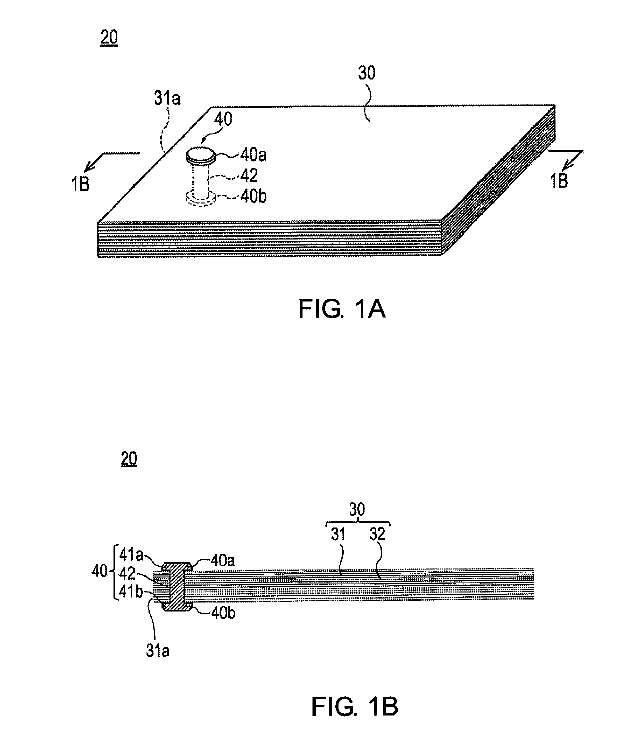
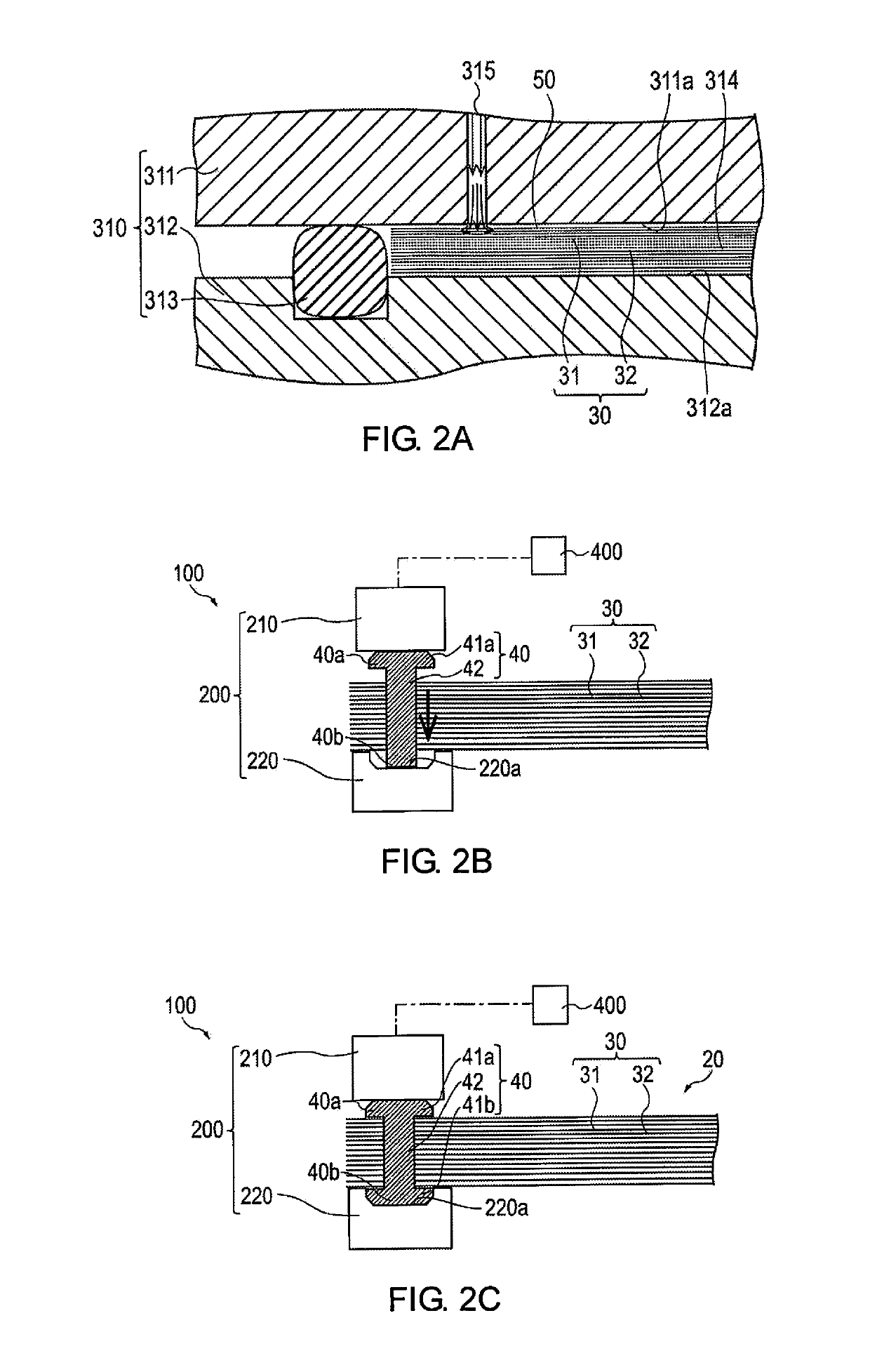
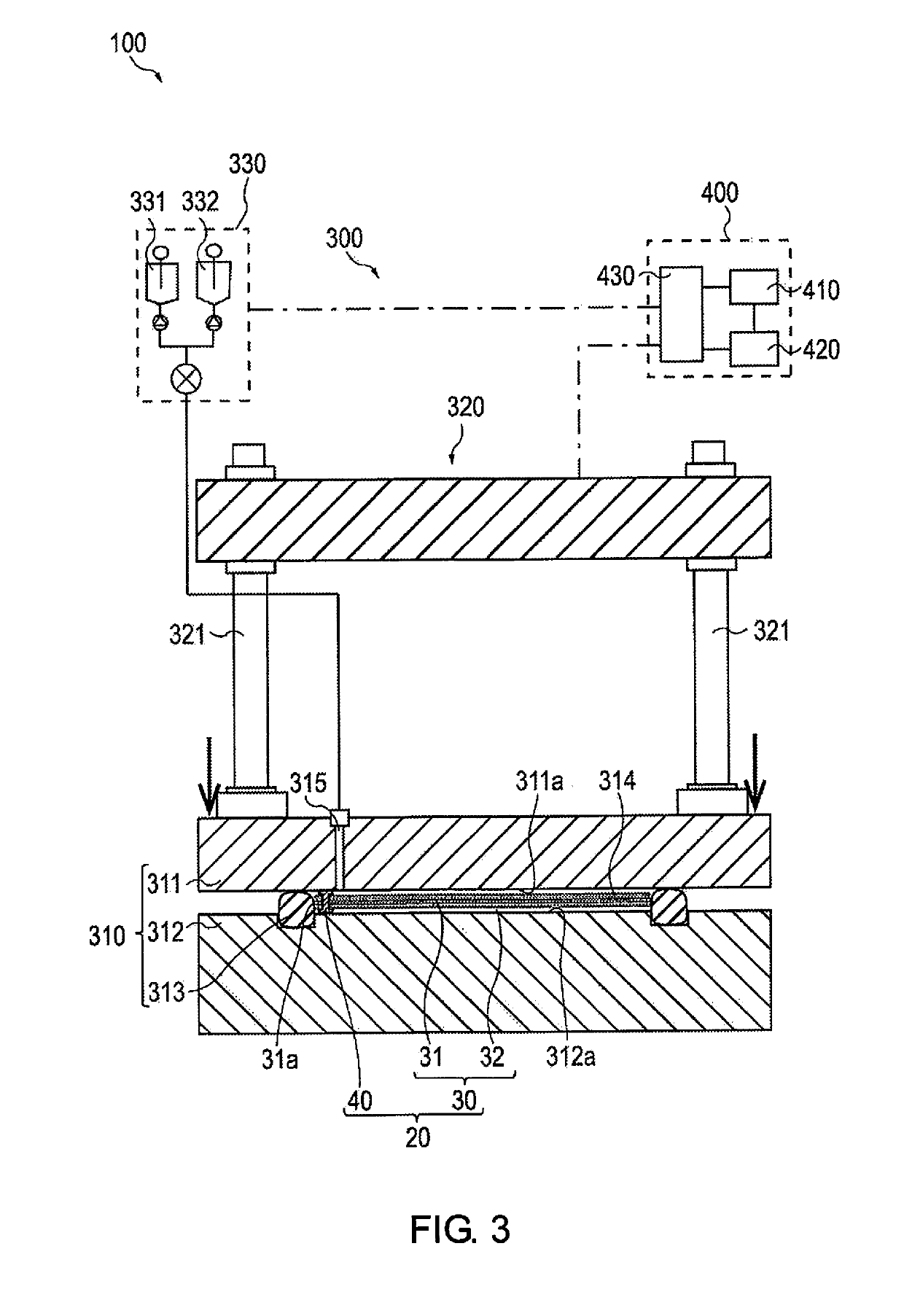
A molding method for a composite material by disposing a reinforcing base material within a cavity of an openable/closable molding die, injecting resin into the cavity and curing the resin. In particular support member is caused to penetrate a reinforcing base material and is disposed such that at least one end portion of the support member projects from the reinforcing base material. Next, the reinforcing base material and the support member are disposed within a cavity of a molding die, the molding die is closed, at least one end portion of the support member is brought into contact with wall surfaces of the molding die that form the cavity. Finally, resin is injected into the cavity from an injection port of the molding die while a state in which the at least one end portion is brought into contact with the wall surface is maintained.

Description

CROSS-REFERENCE TO RELATED APPLICATIONS[0001]This application is a U.S. national stage application of International Application No. PCT / JP2016 / 073493, filed on Aug. 9, 2016.BACKGROUNDTechnical Field[0002]The present invention relates to a molding method and an intermediate member for composite material.Background Information[0003]In recent years, composite materials made by impregnating a reinforcing base material with resin have been used as automobile parts to reduce automobile body weight. An RTM (Resin Transfer Molding) molding method, which is suitable for mass production, is attracting attention as a molding method for composite material. In the RTM molding method, first, a reinforcing base material is placed in a cavity of a molding die, resin in poured into the cavity, the reinforcing base material is impregnated with the resin, and the resin is cured, thereby forming a composite material.[0004]When the resin is poured into the cavity, disorder in the arrangement of the rein...

Claims


Application Information

Patent Timeline
Patent Type & Authority Applications(United States)
IPC IPC(8): B29C70/48B29C70/68
CPCB29C70/48B29C70/68B29C70/541B29C70/543B29C39/10B29C45/14
Inventor OKAI, HIROAKI
Owner NISSAN MOTOR CO LTD
Why Eureka
Try Eureka