Composite Structure Of Composite Substrate And Plastic Material

a composite substrate and composite material technology, applied in the field of composite substrate and plastic material composite structure, can solve the problems of large gaps between the composite substrate and the 3c structural elements, inability to further configure more sophisticated small structures, and large time consumption, so as to improve the appearance quality of the 3c product, prevent the small structure, and save production cost

Inactive Publication Date: 2009-05-28
HUANG CHUN YING +1
View PDF4 Cites 30 Cited by
  • Summary
  • Abstract
  • Description
  • Claims
  • Application Information

AI Technical Summary

Benefits of technology

[0006]A primary objective of the present invention is to provide a composite structure of a composite substrate and a plastic material. The composite substrate and the plastic material are combined together by injection molding, thus achieving an optimal bondability therebetween and can being adapted for mass production.
[0009]Comparing with the conventional technology which combines a small structure onto a composite substrate by gluing, the present invention can advantageously prevent the small structure from undesired detachment from the composite substrate. Further, the small composite structure fabricated by the composite substrate and the plastic material is integral structure. Therefore, when the composite substrate is further assembled to another element of the 3C product, they can be equipped without occurrence of any gap therebetween, thus improving the appearance quality of the 3C product. The present invention is further adapted for mass production, thus saving production cost.

Problems solved by technology

However, such a method is mainly adapted for producing flat or slightly curved composite material plates, and is incapable of further configuring more sophisticated small structures, such as a frame, a boss, or a bezel.
Unfortunately, the method of gluing with the glue-dripping machine often leaves gaps between the composite substrate and the 3C structural elements after the gluing process.
Further, the gluing process requires for many glue-dripping machines and staff, which is expansive and time consuming.

Method used


Image

  • Composite Structure Of Composite Substrate And Plastic Material
  • Composite Structure Of Composite Substrate And Plastic Material
  • Composite Structure Of Composite Substrate And Plastic Material

Examples


Embodiment Construction

[0017]The accompanying drawings are included to provide a further understanding of the invention, and are incorporated in and constitute a part of this specification. The drawings illustrate embodiments of the invention and, together with the description, serve to explain the principles of the invention.

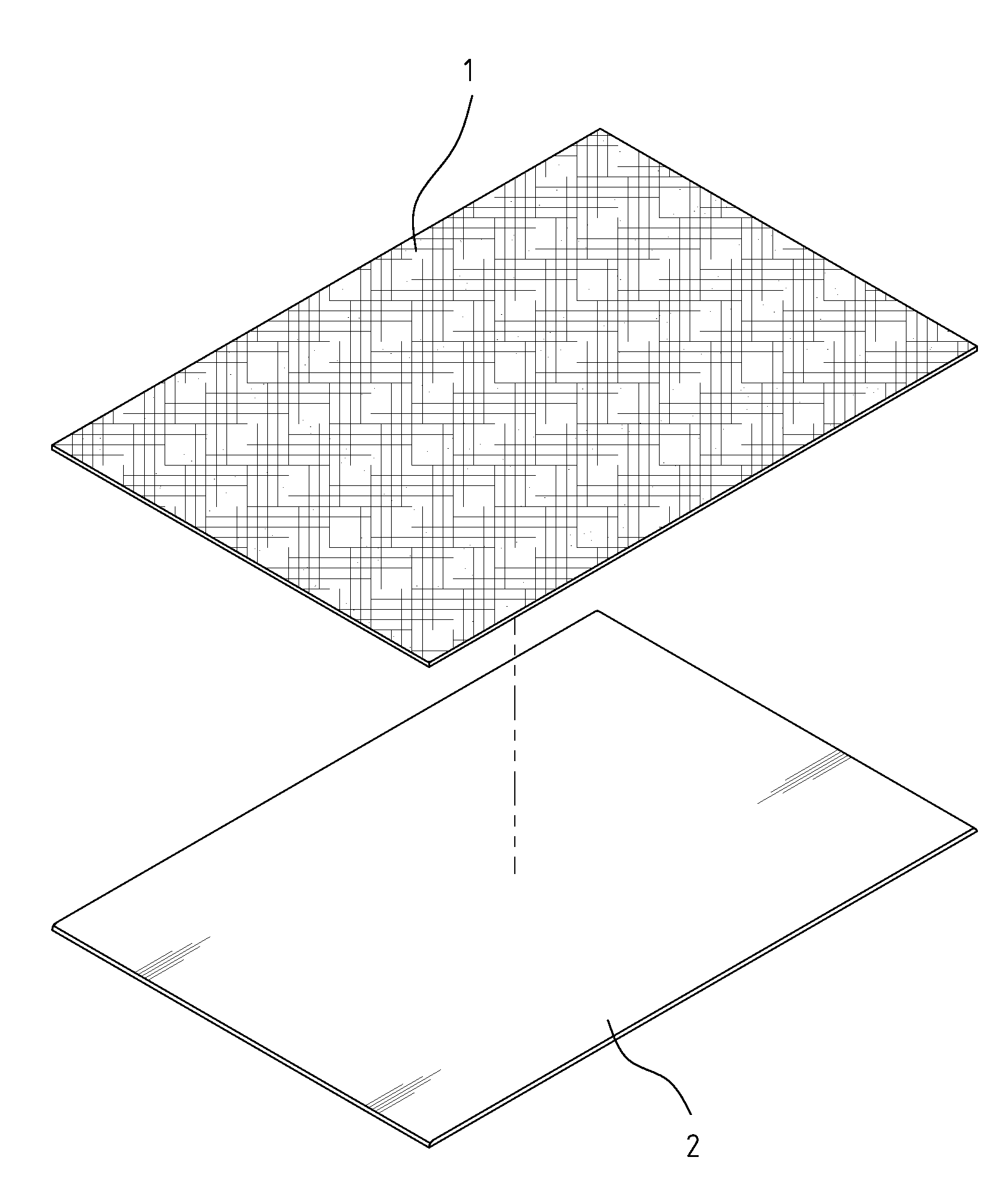
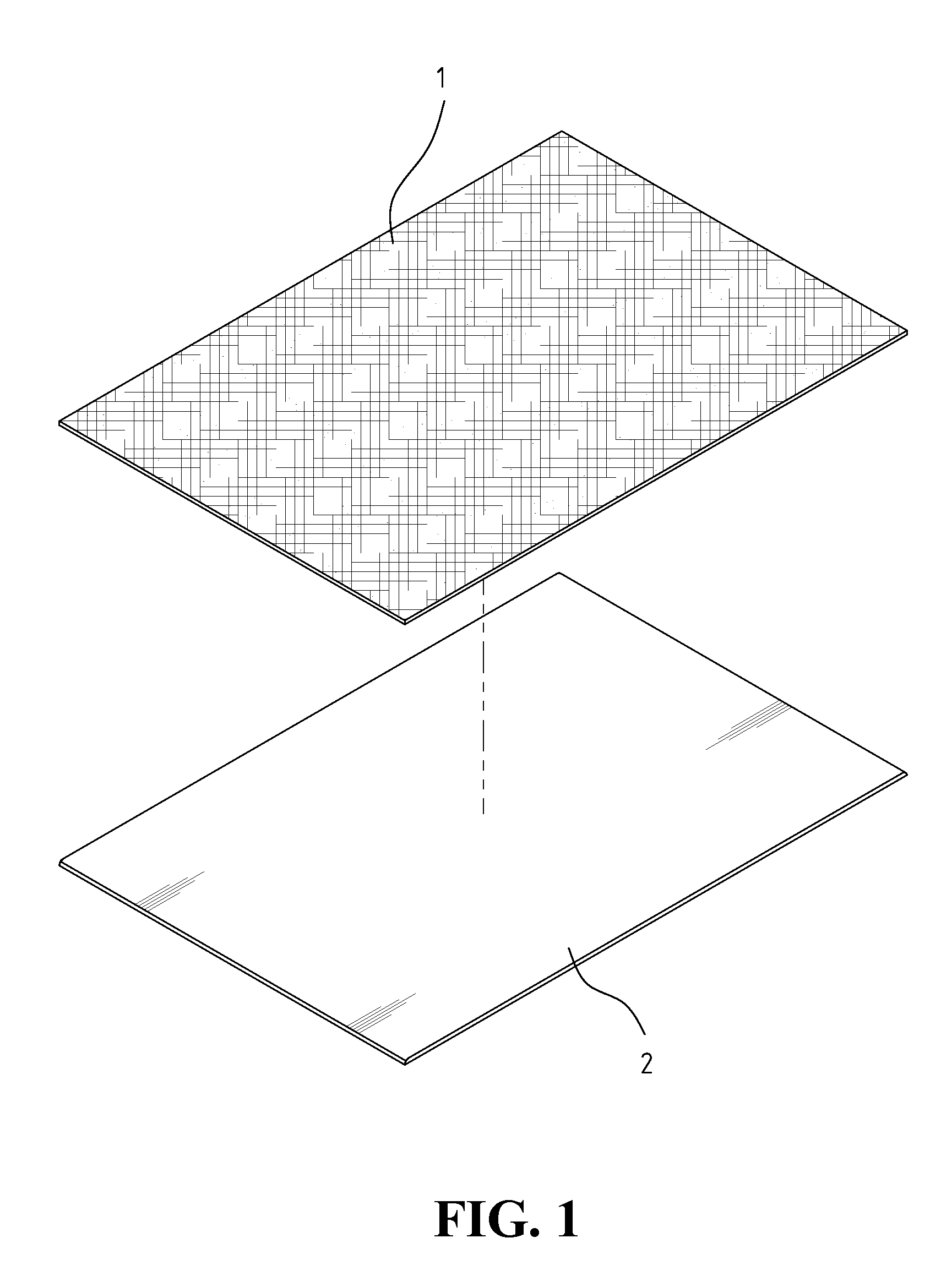
[0018]FIG. 1 is a perspective exploded view of a composite structure of a composite substrate and a plastic material according to an embodiment of the present invention. Referring to FIG. 1, there are shown a composite substrate 1 and a plastic material 2 combined together. The composite structure of the composite substrate 1 and the plastic material 2 is adapted for providing a solution of the difficulty that it is not easy to form a small structure on a composite substrate.

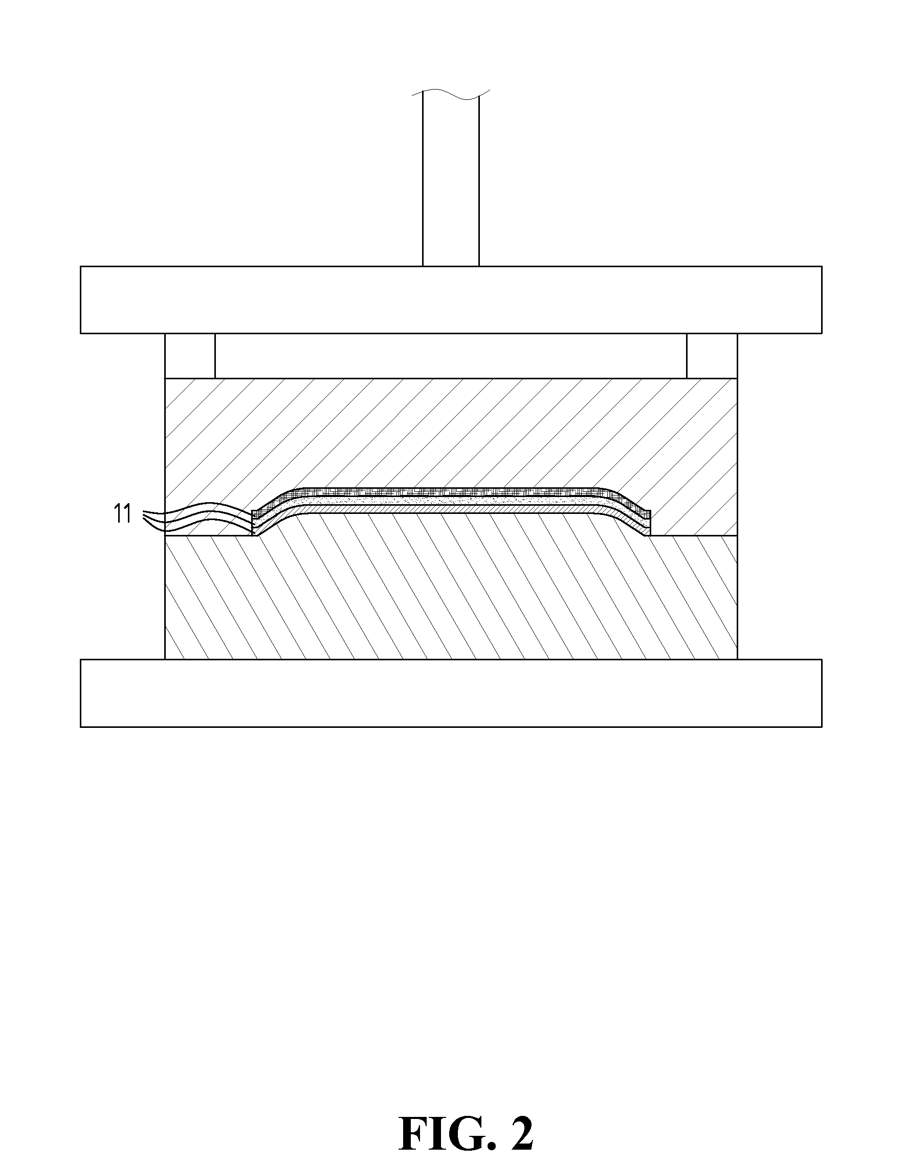
[0019]FIG. 2 is a schematic view illustrating a process of compression molding conducted to the composite substrate according to an embodiment of the present invention. FIG. 3 is a cross-sectional view of the com...


PUM

PropertyMeasurementUnit
temperatureaaaaaaaaaa
structureaaaaaaaaaa

Abstract

A composite structure of a composite substrate and a plastic material is provided. The composite structure is fabricated by a method including the steps of: preparing a plurality of fiber layers weaved in different directions and laminating the fiber layers to configure a stack; soaking the stack in a resin, and drying the soaked stack to obtain a composite substrate; conducting a compression molding process to the composite substrate to achieve a predetermined shape; putting the compression molded composite substrate in a mold of a plastic injection molding machine; injecting a melting plastic material obtained from plastic particles melted by an extrusion machine into the mold, for combining with the composite substrate; and water cooling for hardening the combination, thus achieving a product of the composite structure.

Description

BACKGROUND OF THE INVENTION[0001]1. Field of the Invention[0002]The present invention relates generally to a composite structure of a composite substrate and a plastic material, and more particularly, to a composite structure adapted for simplifying processing process, saving production cost, and improving product quality.[0003]2. The Prior Arts[0004]Composite materials, which are usually featured with advantages such as light weight, strong structural strength, are now widely used in making housings of small electronic products, e.g., notebook computers, mobile phones, or personal digital assistants (PDAs), for replacing plastic housings or serving as enhancement structures of plastic housings.[0005]Typically, conventional composite materials are produced by stacking many layers of fibers together and then configured by compression molding. However, such a method is mainly adapted for producing flat or slightly curved composite material plates, and is incapable of further configuri...

Claims


Application Information

Patent Timeline
Patent Type & Authority Applications(United States)
IPC IPC(8): B32B5/12B29C67/00
CPCB29C45/1418Y10T428/24124B29C45/14786B29C70/086B29C70/46B32B27/12B32B27/32B32B5/024B32B5/12B32B27/302B32B27/304B32B27/365B32B3/28B32B3/30B32B2260/023B32B2260/046B32B2262/0269B32B2262/101B32B2307/50B32B2307/536B32B2307/718B32B2457/00B29C45/14631
Inventor HUANG, CHUN-YINGCHEN, WEI-JEN
Owner HUANG CHUN YING
Why Eureka
Try Eureka