[0008]It is therefore the object of the invention to provide for possibilities of a safer transport and / or lifting of large scale generators.
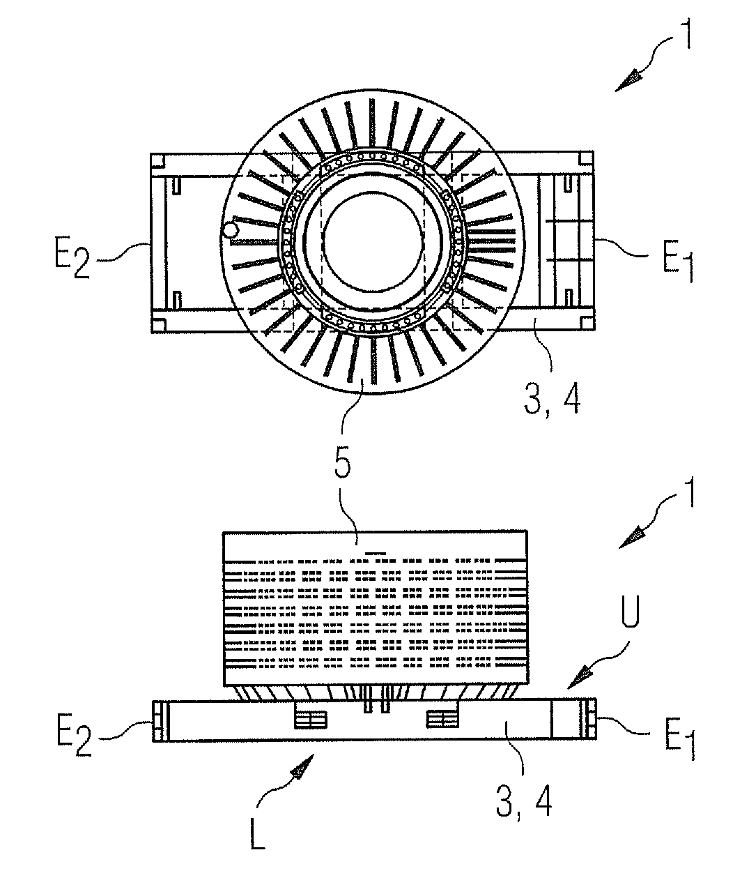
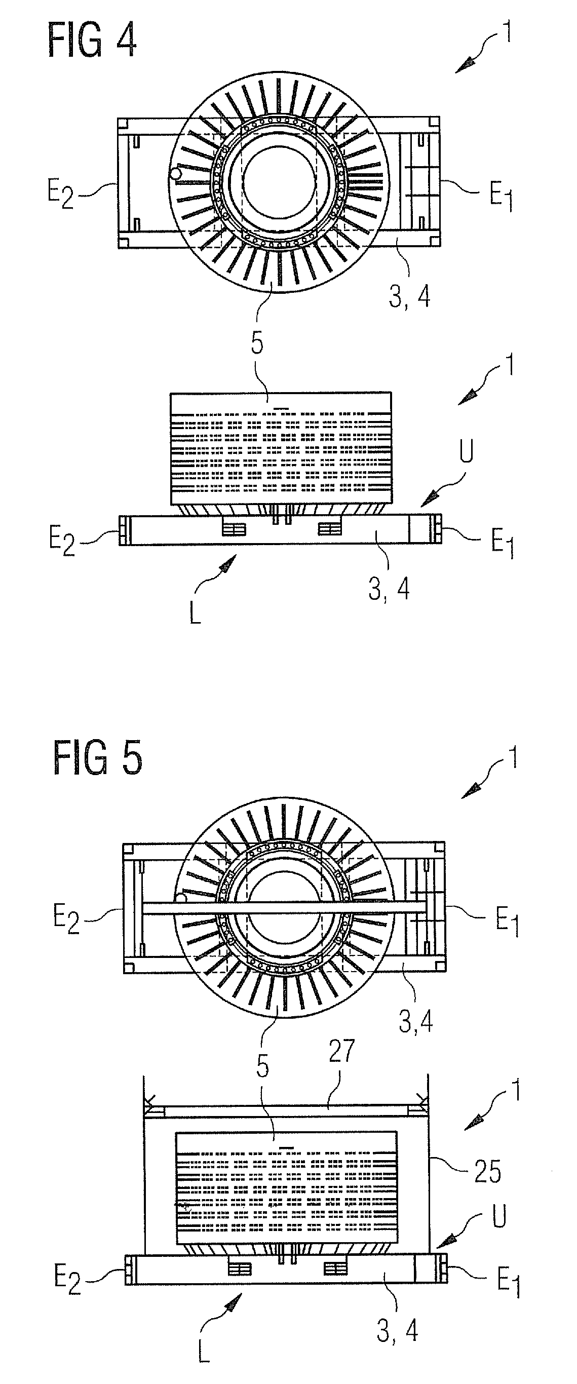
[0020]Concerning the method for lifting a large scale generator, this is realized by attaching the generator to a transport structure via an interface arrangement of the transport structure in the direction of an upper side of the transport structure and by moving the transport structure from a position in which its main extension is essentially orientated in a horizontal way into a position in which its main extension is essentially orientated in a vertical way. That implies that not only the generator itself is brought into an assembly position during lifting but also the transport structure, which is still connected to the generator. This means that chains or lashes need not necessarily be attached to the generator itself, but can rather be connected to the transport structure instead. This way there is no connection between the chains and the generator so that the danger of damaging the generator during the lifting procedure is substantially reduced. Such a lifting procedure is particularly advantageous in the connection with the transport method according to the invention: once the generator has been connected to the transport structure it can be transported by any kind of means of transport on the transport structure without being removed from it at any time. Even during the preparation of assembly of the generator in its assembly position, for instance in a wind turbine, it still is connected to the same transport structure which now serves as a kind of carrier or intermediate between chains or other parts connected to a lifting device and the generator. Thus, the user of such transport structure in the context of both transporting and lifting the generator has the positive effect of reduced time, effort and costs for transport and assembly of the generator. One can conclude that once the connection between the generator and the transport structure has been established it will not be loosened until the generator is assembled at its point of destination. This connection can be established right after the end of construction of the generator, but also before that: during the construction the transport structures may already serve as kinds of platforms in the context of an assembly line.
[0021]The point of destination is preferably a wind turbine, in particular a large wind turbine with a maximum power output of at least 100 KW, preferably of at least 2 MW, most preferred of at least 5 MW. Connected to an assembly in such wind turbines there firstly is the problem that the generators have to be lifted very high above ground, i.e. about 60 m or more, so that lifting the generator is particularly difficult. Secondly such wind turbines require very large generators so that the transport of these generators is particularly difficult as well. Thirdly, generators for wind turbines have particularly high requirements concerning their reliability: due to the great effort needed for transporting and lifting generators for assembly in a wind turbine, an exchange if such a generator should not work properly is particularly tedious and costly as well. Therefore, it is a highly critical task to avoid critical transport damages or damages during lifting the generator to the wind turbine. The transport structure according to the invention which ensures a substantial reduction of danger of damage to the generator in comparison with the state of the art is therefore highly advantageous in particular for wind turbine generators.
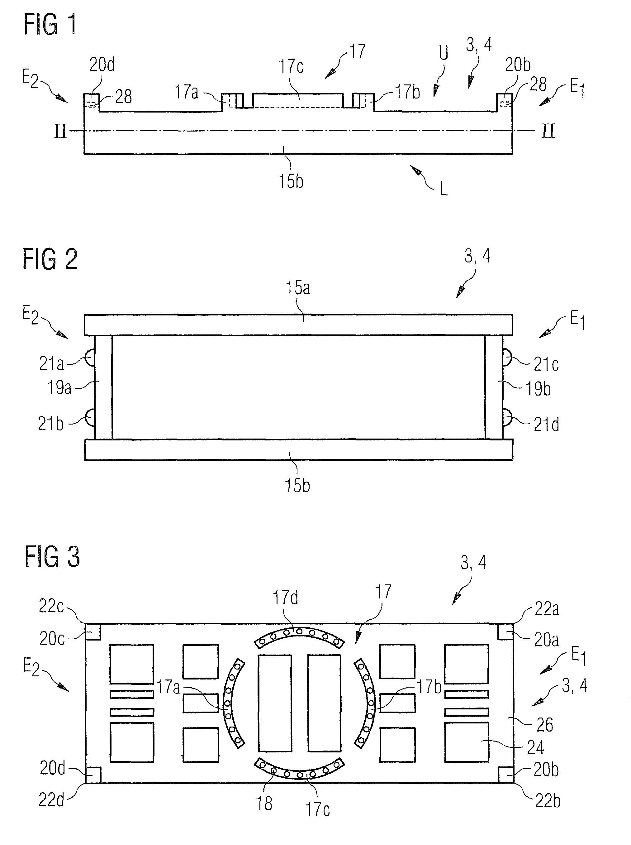
[0026]The handling base can virtually be made up of any kind of elements serving to establish a stable carrier structure, for example one or several metal plates. It is preferred that the handling base comprises at least one longitudinal beam and at least one cross beam orientated in an essentially perpendicular way to the longitudinal beam. These two beams are interconnected and can thus constitute a stable carrier structure, if wished for in combination with other elements such as metal plates etc. Using such beam structure based on at least one longitudinal beam and one cross beam serves to establish a reasonably stable handling base with low effort and costs. Preferably there are at least two longitudinal beams and / or two cross beams, most preferred is a combination of at least two longitudinal beams and at least two cross beams which then can all be placed in the region of the edges of the handling base to essentially define its limits. The longitudinal and or cross beam(s) can be realized as a metal beam(s), for instance in an H shape in their cross section. The longitudinal and cross beam(s) can be connected in such way that a forklift can be placed underneath them or within their cross sectional shape. This facilitates raising the transport structure by a forklift. However, a forklift can also be placed inside of specially designated holes within any of the mentioned beams or in to any other orifices in the handling base.
[0030]Also for land transport it is advantageous if at the first longitudinal end of the transport structure there is an interface for attachment of the handling base to a tractor. As mentioned above, a truck master or a similar transport means can pull the handling base so that the transport structure itself need not be equipped with a motor unit of its own. The interface for the attachment to a tractor therefore serves to supply the possibility of a releasable connection between a tractor and the transport structure. Establishing a releasable connection also implies that the transport structure can be taken off the tractor again, e.g. for sea transport.
[0031]It is also preferred that the transport structure comprises connecting means for connecting the handling base directly or indirectly to a lifting device such as a crane or a helicopter. That connecting means may comprise one or several holes and / or fittings which are positioned such that chains or ropes leading to the lifting device can be attached to the transport structure in such a way that a stable lifting process can be realized. Therefore, it is particularly advantageous to have at least three such connecting means, preferably at least for, which latter are advantageously arranged symmetrically such that during a lifting processors the transport structure is not in danger of tilting away uncontrollably.


