Adjacent joint space trajectory transition method and device

A joint space and trajectory technology, which is applied in the direction of program control manipulators, manufacturing tools, manipulators, etc., can solve the problems of high time cost and energy consumption cost, and achieve the effect of reducing time cost and energy consumption cost, and reducing start-up and stop

Active Publication Date: 2021-01-08
合肥哈工图南智控机器人有限公司
View PDF5 Cites 1 Cited by
  • Summary
  • Abstract
  • Description
  • Claims
  • Application Information

AI Technical Summary

Problems solved by technology

[0003] The technical problem to be solved by the present invention lies in the high time cost and high energy consumption cost of the prior art adjacent joint space trajectory transition method

Method used


Image

  • Adjacent joint space trajectory transition method and device
  • Adjacent joint space trajectory transition method and device
  • Adjacent joint space trajectory transition method and device

Examples


Embodiment 1

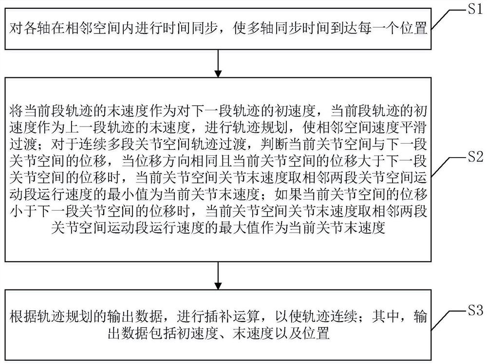
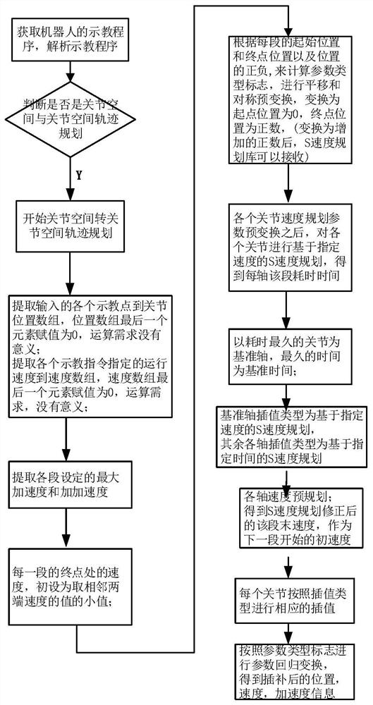
[0029] Such as figure 1 As shown in Fig. 1 , a method for the transition of adjacent joint space trajectories, the transition of adjacent joint space trajectories is mainly that the final velocity of the previous joint space command is used as the initial velocity of the next joint space command, and at the same time, the time synchronization of each motion axis of each joint space command is performed. . The methods include:

[0030] Step S1: Perform time synchronization for each axis in the adjacent space, so that the multi-axis synchronization time reaches each position. Each axis first calculates the single-segment PTP running time of each axis according to the input information and parameter adaptive S-speed planning, and then uses the maximum running time of each axis as the reference time, and other axes do S-speed planning based on the reference time , to realize the time synchronization of each axis of the single-segment PTP; among them, the parameter adaptive S spe...

Embodiment 2

[0045] Corresponding to Embodiment 1 of the present invention, Embodiment 2 of the present invention also provides an adjacent joint space trajectory transition device, which includes:

[0046] The time synchronization module is used to synchronize the time of each axis in the adjacent space, so that the multi-axis synchronization time reaches each position;

[0047] The trajectory planning module is used to use the terminal velocity of the current segment trajectory as the initial velocity of the next segment trajectory, and the initial velocity of the current segment trajectory as the terminal velocity of the previous segment trajectory, and perform trajectory planning to make the adjacent space velocity smooth transition; for continuous Multi-segment joint space trajectory transition, judging the displacement between the current joint space and the next joint space, when the displacement direction is the same and the displacement of the current joint space is greater than th...


PUM


Abstract

The invention discloses an adjacent joint space trajectory transition method and device. The adjacent joint space trajectory transition method comprises the steps that time synchronization is carriedout on all shafts in an adjacent space to enable the synchronization time of the shafts to reach each position; the final speed of a current segment of a trajectory is taken as the initial speed of anext segment of the trajectory, the initial speed of the current segment of the trajectory is taken as the final speed of the previous segment of the trajectory, and trajectory planning is carried outto enable the speeds of adjacent spaces to be in smooth transition; and interpolation operation is carried out according to output data of the trajectory planning so as to enable the trajectory to becontinuous. The adjacent joint space trajectory transition method and device have the advantages that the spot speed of each intermediate process is smooth, unnecessary start and stop are reduced, and time cost and energy consumption cost are reduced.

Description

technical field [0001] The invention relates to the field of robot motion control, and more particularly relates to a method and device for transitioning adjacent joint space trajectories. Background technique [0002] The movement space of the manipulator is divided into joint space and Cartesian space. At present, the movement of industrial manipulators in a single joint space and Cartesian space is very easy to realize. The main method of mixed space transition between joint space and Cartesian space is to transfer the joint space to Cartesian space through forward kinematics, and then perform trajectory transition between Cartesian space and Cartesian space instructions, such as slowing down at the intersection point to Zero processing. For the joint space planning of a universal robot, that is, PTP, each joint is often planned separately from the starting point to the ending point, and each joint can be started at the same time and reach the specified point. Such a si...

Claims


Application Information

Patent Timeline
IPC IPC(8): B25J9/16
CPCB25J9/1664B25J9/1602
Inventor 刘鹏飞杨健刘勋王权
Owner 合肥哈工图南智控机器人有限公司
Why Eureka
Try Eureka