Linear vibrator

a linear and vibrator technology, applied in the direction of dynamo-electric machines, electrical apparatus, etc., can solve the problems of shortening the life of the motor, affecting the effect of the vibration of the touch screen, and a large amount of time to reach, so as to achieve the effect of smooth flow into the magn

Inactive Publication Date: 2014-10-14
MPLUS
View PDF17 Cites 1 Cited by
  • Summary
  • Abstract
  • Description
  • Claims
  • Application Information

AI Technical Summary

Benefits of technology

[0015]An aspect of the present invention provides a linear vibrator allowing for miniaturization and slimness thereof by changing configurations of a coil and a magnet generating electromagnetic force for vibrations, while having no change in performance and characteristics thereof due to elements vibrating therein.

Problems solved by technology

However, in such a brush type configuration using a commutator, the brush may cause mechanical friction and electrical sparks when passing through a gap between segments of the commutator during rotation of the motor, and may generate foreign substances, thereby shortening a lifespan of the motor.
Also, it may take a great deal of time to reach a target amount of vibrations, due to rotational inertia when voltage is applied to the motor, and thus, there may be a limitation in realizing suitable touch screen vibrations.
A linear vibrator does not use the rotating principle of the motor, and may periodically generate electromagnetic force through a spring installed in the linear vibrator and a mass body suspended from the spring according to a resonant frequency to cause resonance, thereby generating vibrations.
However, a linear vibrator according to the related art may cause a change in the performance and characteristics thereof due to elements that vibrate therein, and as a result, may affect the performance of a mobile electronic device employing the linear vibrator.

Method used


Image

  • Linear vibrator
  • Linear vibrator
  • Linear vibrator

Examples


Embodiment Construction

[0042]Embodiments of the present invention will now be described in detail with reference to the accompanying drawings. However, it should be noted that the spirit of the present invention is not limited to the embodiments set forth herein and those skilled in the art and understanding the present invention could easily accomplish retrogressive inventions or other embodiments included in the spirit of the present invention by the addition, modification, and removal of components within the same spirit, but those are to be construed as being included in the spirit of the present invention.

[0043]Further, throughout the drawings, the same or similar reference numerals will be used to designate the same or like components having the same functions in the scope of the similar idea.

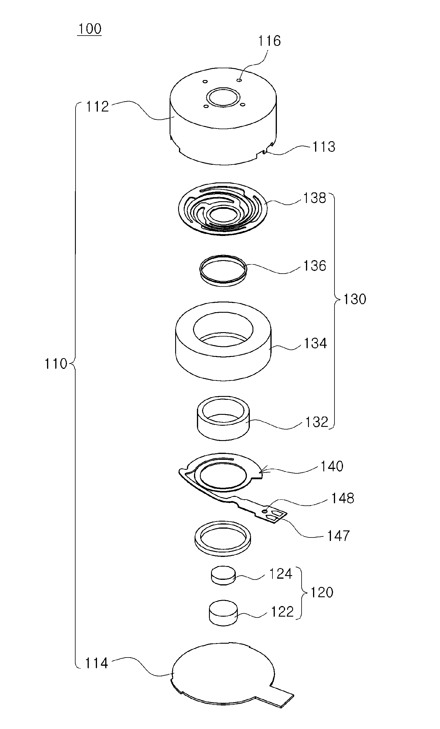
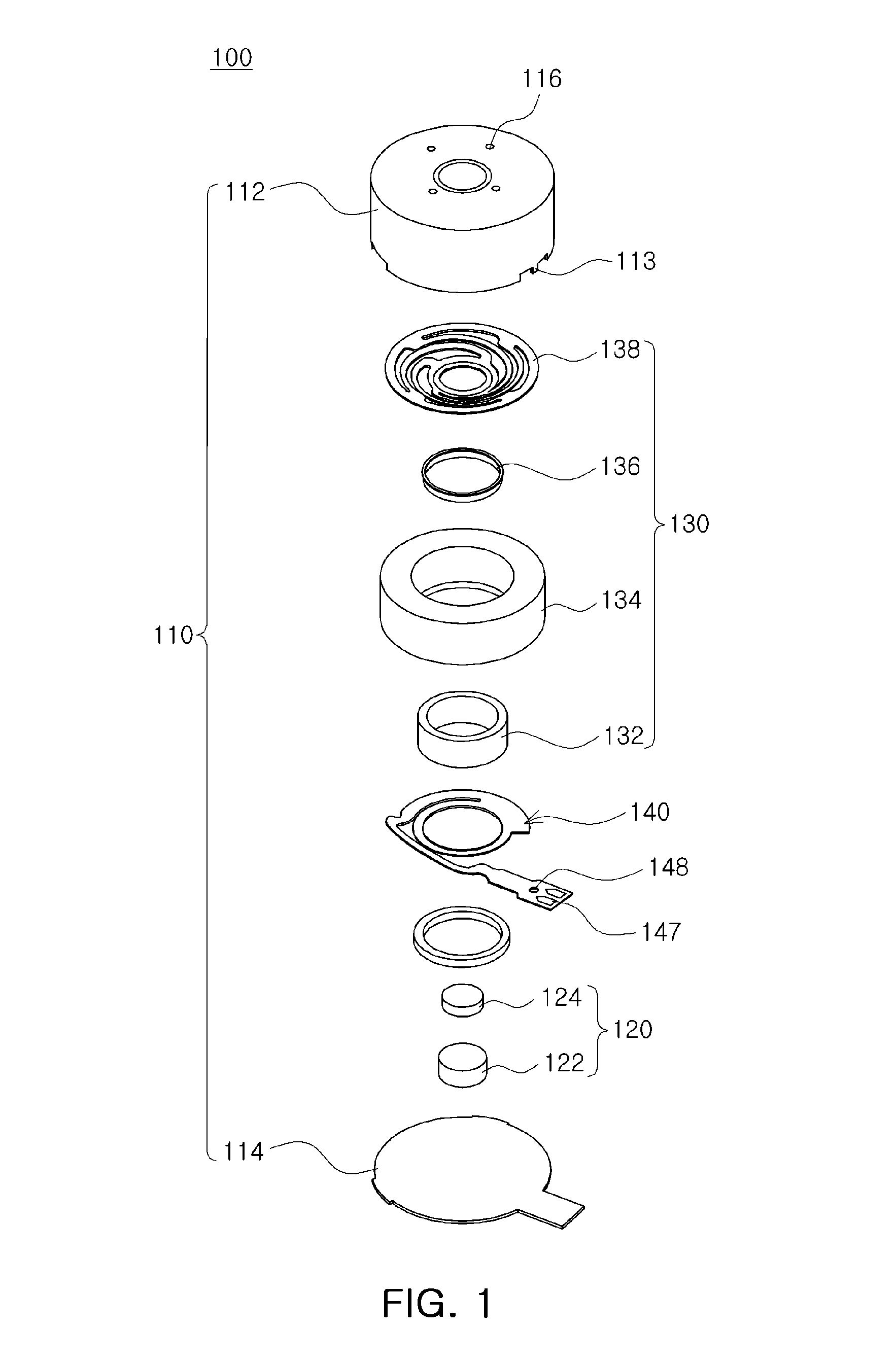
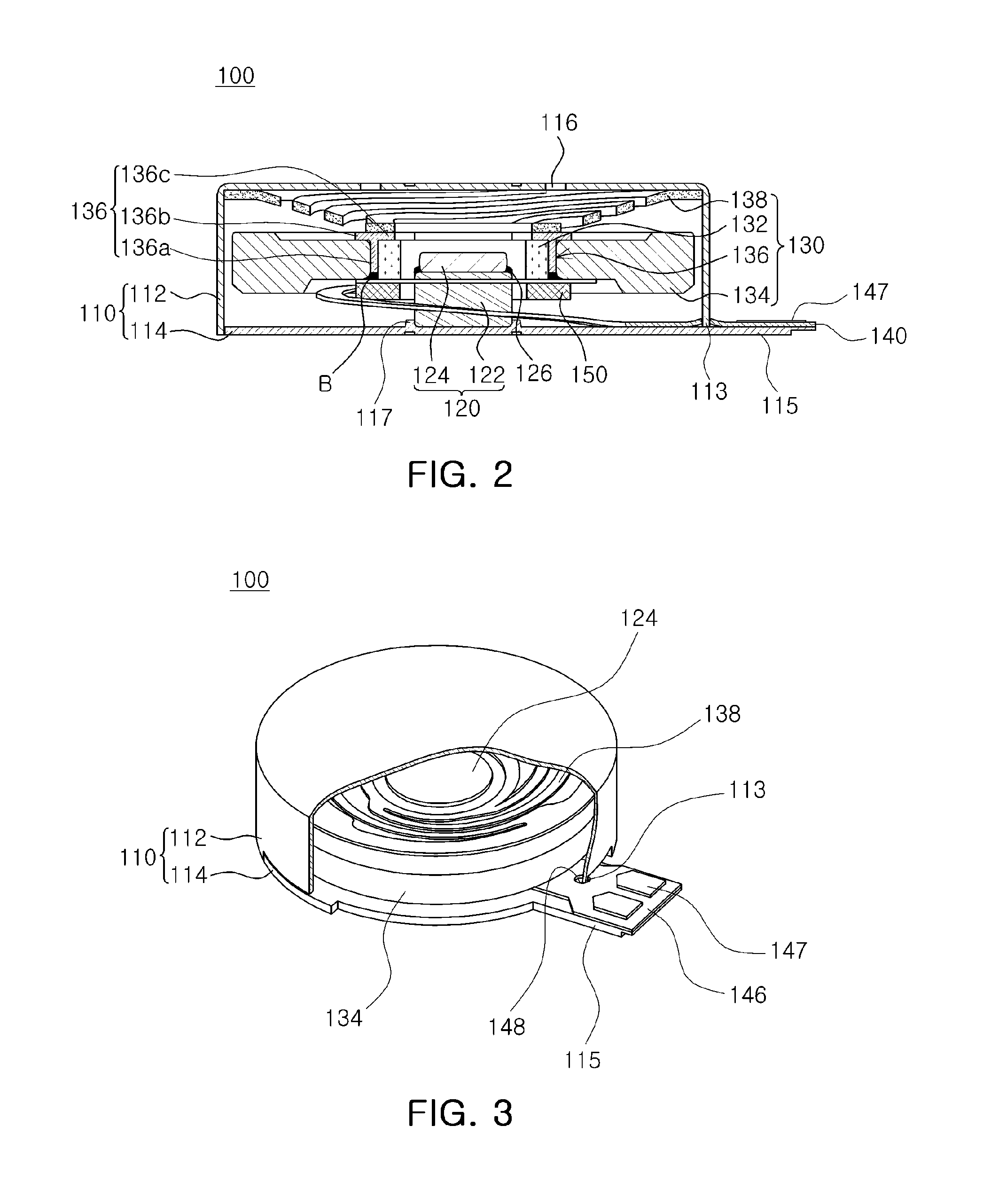
[0044]FIG. 1 is a schematic exploded perspective view illustrating a linear vibrator according to an embodiment of the present invention. FIG. 2 is a schematic cross sectional view illustrating the linear vibra...


PUM


Abstract

There is provided a linear vibrator, including a fixed part having an inner space of a predetermined size formed therein; at least one magnet disposed in the inner space and generating magnetic force; a vibration part including a coil disposed to face the magnet to generate electromagnetic force through interaction therewith, and a mass body; a substrate having one end connected to the vibration part to serve as a free end, and the other end connected to the fixed part to serve as a fixed end; and a connection protrusion formed on the fixed part and inserted into a connection hole formed in the substrate so as to allow the substrate to be fixed to the fixed part.

Description

CROSS-REFERENCE TO RELATED APPLICATIONS[0001]This application claims the priority of Korean Patent Application No. 10-2011-0089605 filed on Sep. 5, 2011, in the Korean Intellectual Property Office, the disclosure of which is incorporated herein by reference.BACKGROUND OF THE INVENTION[0002]1. Field of the Invention[0003]The present invention relates to a linear vibrator, and more particularly, to a linear vibrator mounted in a mobile electronic device and applied to an apparatus for generating a soundless reception signal.[0004]2. Description of the Related Art[0005]In recent years, personal mobile terminals having large LCD screens have increased for the sake of user convenience. Accordingly, a touch screen method is adopted therein, and a vibration motor is used to generate vibrations when the touch screen is touched.[0006]The vibration motor is an element that converts electrical energy into mechanical vibrations using the principle of generating electromagnetic force, and is mou...

Claims


Application Information

Patent Timeline
Patent Type & Authority Patents(United States)
IPC IPC(8): H02K35/00
CPCH02K33/18H02K33/02
Inventor KIM, JIN, HOON
Owner MPLUS
Why Eureka
Try Eureka