Ventilated hydrofoils for watercraft

a technology of hydrofoil and watercraft, which is applied in the direction of marine propulsion, special-purpose vessels, vessel construction, etc., can solve the problems of excessive pressure drag in this case, and achieve the effect of less prone to uncontrollable pitch divergence and high stalling angl

Inactive Publication Date: 2014-10-21
HOWES JONATHAN SEBASTIAN +1
View PDF9 Cites 5 Cited by
  • Summary
  • Abstract
  • Description
  • Claims
  • Application Information

AI Technical Summary

Benefits of technology

[0010]The present applicants have identified the need for a simple robust hydrofoil system together with constructional techniques and configurations for deploying it advantageously on water craft such that the said craft inherently maintains an appropriate ride height, has good lift-drag characteristics at low speed and transitions smoothly between non-ventilated and ventilated operation and further, does not suffer any adverse effects when the hydrofoils ventilate and does not suffer any significant degradation of performance at high speed due to cavitation.

Problems solved by technology

As all load is carried on the first face flow separation is rarely a concern and the maximum mean pressure coefficient can approach unity although the pressure drag in this case would be excessively high.

Method used


Image

  • Ventilated hydrofoils for watercraft
  • Ventilated hydrofoils for watercraft
  • Ventilated hydrofoils for watercraft

Examples


Embodiment Construction

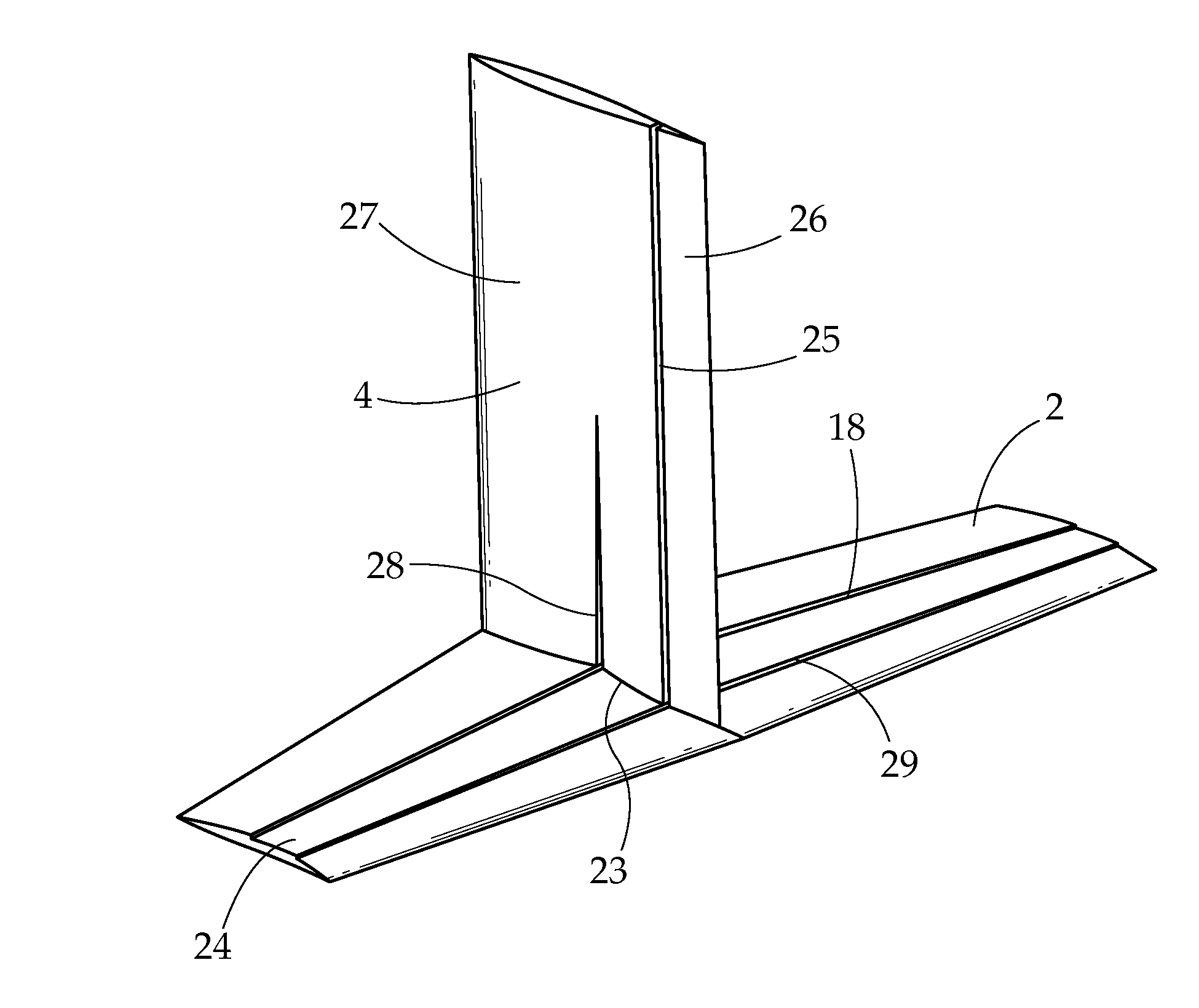
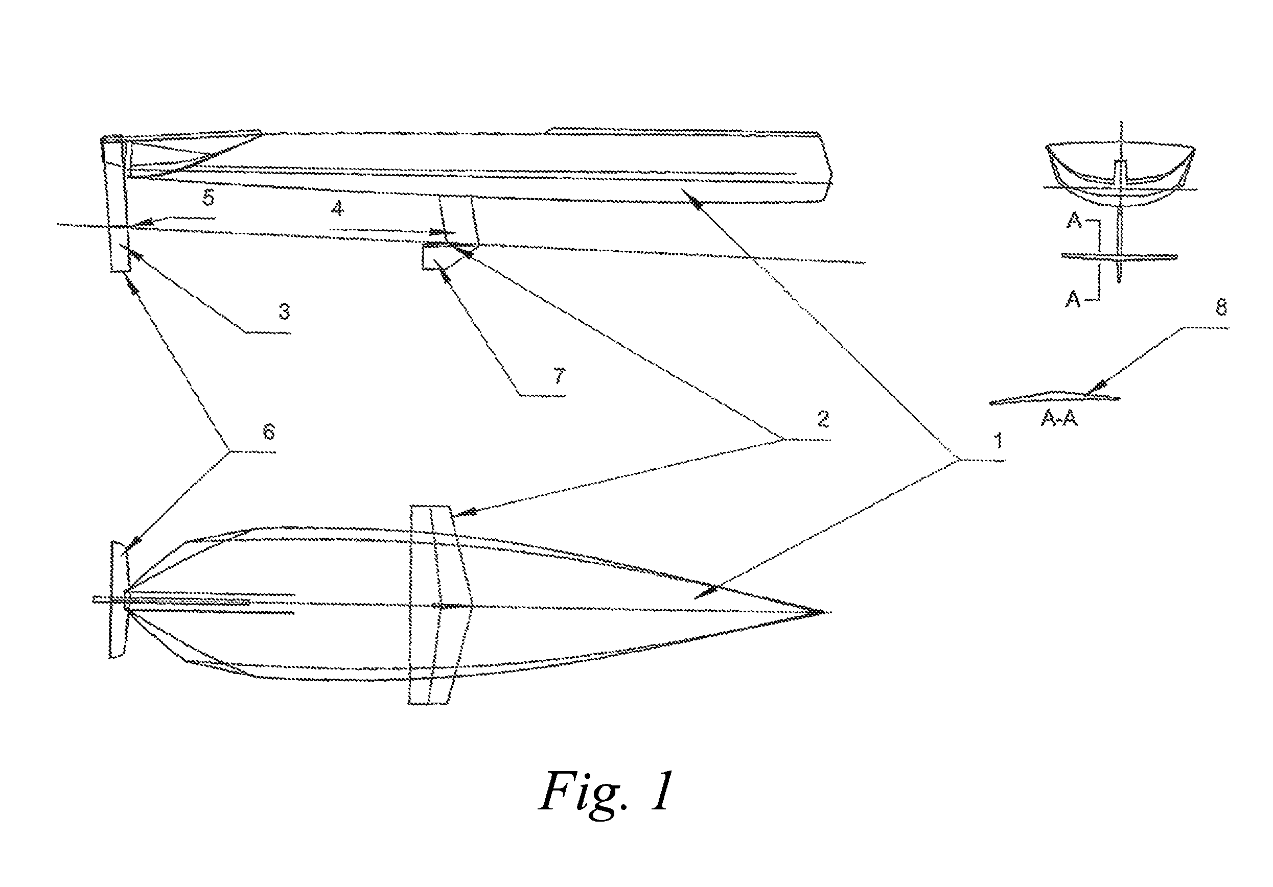
[0053]By reference to FIG. 1 a typical installation of a hydrofoil in accordance with the present invention may be described. From the hull means (1) depends a substantially vertical strut (4) to which, at the foil-borne water surface is attached a substantially horizontal hydrofoil means (2), below this hydrofoil (2) is a further substantially vertical surface (7) which provides lateral resistance when the vessel is foil-borne with the foil (2) at the water surface. A further foil (6) is mounted on the rudder (3) to act as a stabilising surface. This may be of conventional non-ventilating and non-cavitating form and configured to operate fully submerged. To provide a means of keeping the primary foil (2) at the correct incidence a second foil (5) may be attached to the rudder at a height setting coinciding with the foil-borne water surface. This second foil (5) may advantageously be of ventilated form to allow consistent surface running operation. The primary foil (2) and the secon...


PUM


Abstract

A hydrofoil section comprises first and second faces that create, in operation at speeds above a ventilation speed, a ventilated cavity defined by a first cavity face which departs from the first hydrofoil face and a second cavity face which departs from the second hydrofoil face. Each cavity face represents a free surface and each face separating from the said free surface at a discontinuity on that surface, the separated faces forming a continuation of the faces of arbitrary shape and enclosed by the free surfaces without contacting the said free surfaces. Below the speed at which full ventilation occurs the arbitrarily shaped portion of each face is configured to provide a modified flow configuration resulting in changed lift and or drag and or pitching moment under partial, or unventilated operation.

Description

CROSS REFERENCE TO RELATED APPLICATION[0001]This application is for entry into the U.S. National Phase under §371 for International Application No. PCT / GB2009 / 000615 having an international filing date of Mar. 6, 2009, and from which priority is claimed under all applicable sections of Title 35 of the United States Code including, but not limited to, Sections 120, 363 and 365(c), and which in turn claims priority under 35 USC §119 to U.K. Patent Application No. 0806523.6 filed on Mar. 28, 2008 and to U.K. Patent Application No. 0813286.9 filed on Jul. 21, 2008.BACKGROUND OF THE INVENTION[0002]1. Field of the Invention[0003]The present invention relates to the design, configuration and construction of improved ventilated hydrofoils and their use in wind and motor driven watercraft.[0004]2. Description of the Related Prior Art[0005]Hydrofoils are widely used in both motor and wind powered water craft with the aim of reducing drag and / or improving passenger comfort by lifting the hull ...

Claims


Application Information

Patent Timeline
Patent Type & Authority Patents(United States)
IPC IPC(8): B63B1/24
CPCB63B1/248B63B1/04B63B2035/009
Inventor HOWES, JONATHAN SEBASTIANJENKINS, LINTON PAUL CHRISTOPHER
Owner HOWES JONATHAN SEBASTIAN
Why Eureka
Try Eureka