Digital delay-locked loop circuit using phase-inversion algorithm and method for controlling the same

a phase-inversion algorithm and delay-locked loop technology, applied in the direction of electrical equipment, pulse automatic control, etc., can solve the problems of difficult to easily apply the analog delay-locked loop circuit to various systems, difficult to widen the operation frequency of the analog delay-locked loop circuit, and the delay may not be precisely controlled by the digital delay-locked loop circuit. , to achieve the effect of short locking time, low power consumption and wide operating frequency rang

Inactive Publication Date: 2014-10-21
HONGIK UNIV IND ACAD COOP FOUND
View PDF18 Cites 5 Cited by
  • Summary
  • Abstract
  • Description
  • Claims
  • Application Information

AI Technical Summary

Benefits of technology

[0012]Accordingly, the present invention has been made keeping in mind the above problems occurring in the prior art, and an object of the present invention is to provide a delay-locked loop circuit using a phase inversion locking algorithm and a method of controlling the same, which are capable of having a wide operating frequency range, a short locking time, low power, a small chip area, and an improved jitter characteristic by minimizing the amount of generated delay time that limits the improvement of performance and availability of the delay-locked loop circuit.

Problems solved by technology

It is however difficult to easily apply the analog delay-locked loop circuit to various systems because the analog delay-locked loop circuit has low transplantation due to a characteristic sensitive to a change in the process of an analog circuit and sensitively responds to the noise of a control signal.
Furthermore, it is difficult for the analog delay-locked loop circuit to have a wide operating frequency due to a long locking time and a non-linear characteristic of a voltage control delay line.
However, the digital delay-locked loop circuit may not precisely control delay because the digital delay-locked loop circuit uses discontinuous digital control information unlike the analog delay-locked loop circuit that uses continuous analog control information and thus it has low resolution of a controllable delay amount.
Such a delay time is the most basic factor that limits the improvement of performance and availability of a delay-locked loop circuit that needs to implement a wide operating frequency range, high delay resolution, low power consumption, a small chip area, and high jitter performance.

Method used


Image

  • Digital delay-locked loop circuit using phase-inversion algorithm and method for controlling the same
  • Digital delay-locked loop circuit using phase-inversion algorithm and method for controlling the same
  • Digital delay-locked loop circuit using phase-inversion algorithm and method for controlling the same

Examples


Embodiment Construction

[0035]Hereinafter, some exemplary embodiments of the present invention are described in detail with reference to the accompanying drawings.

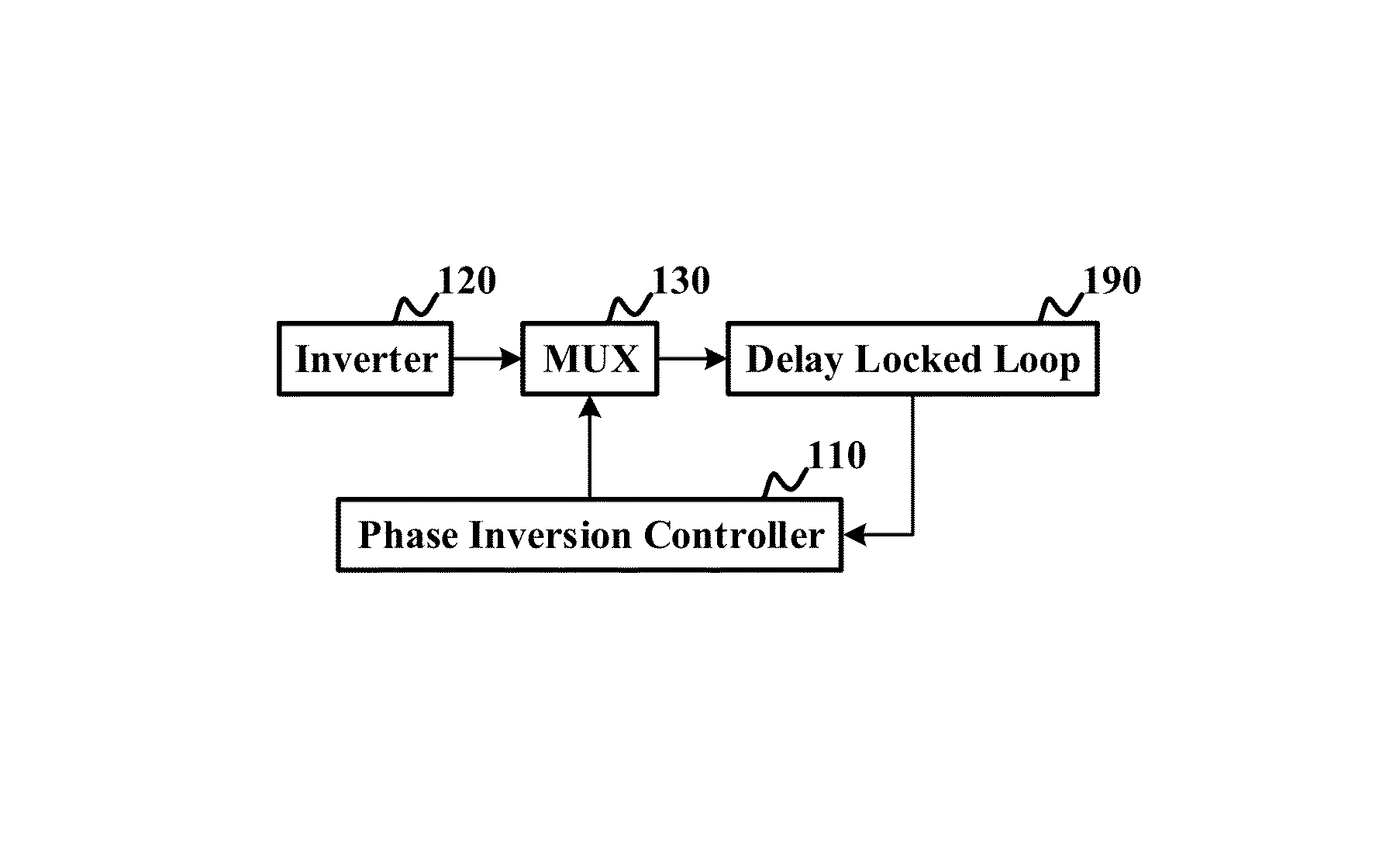
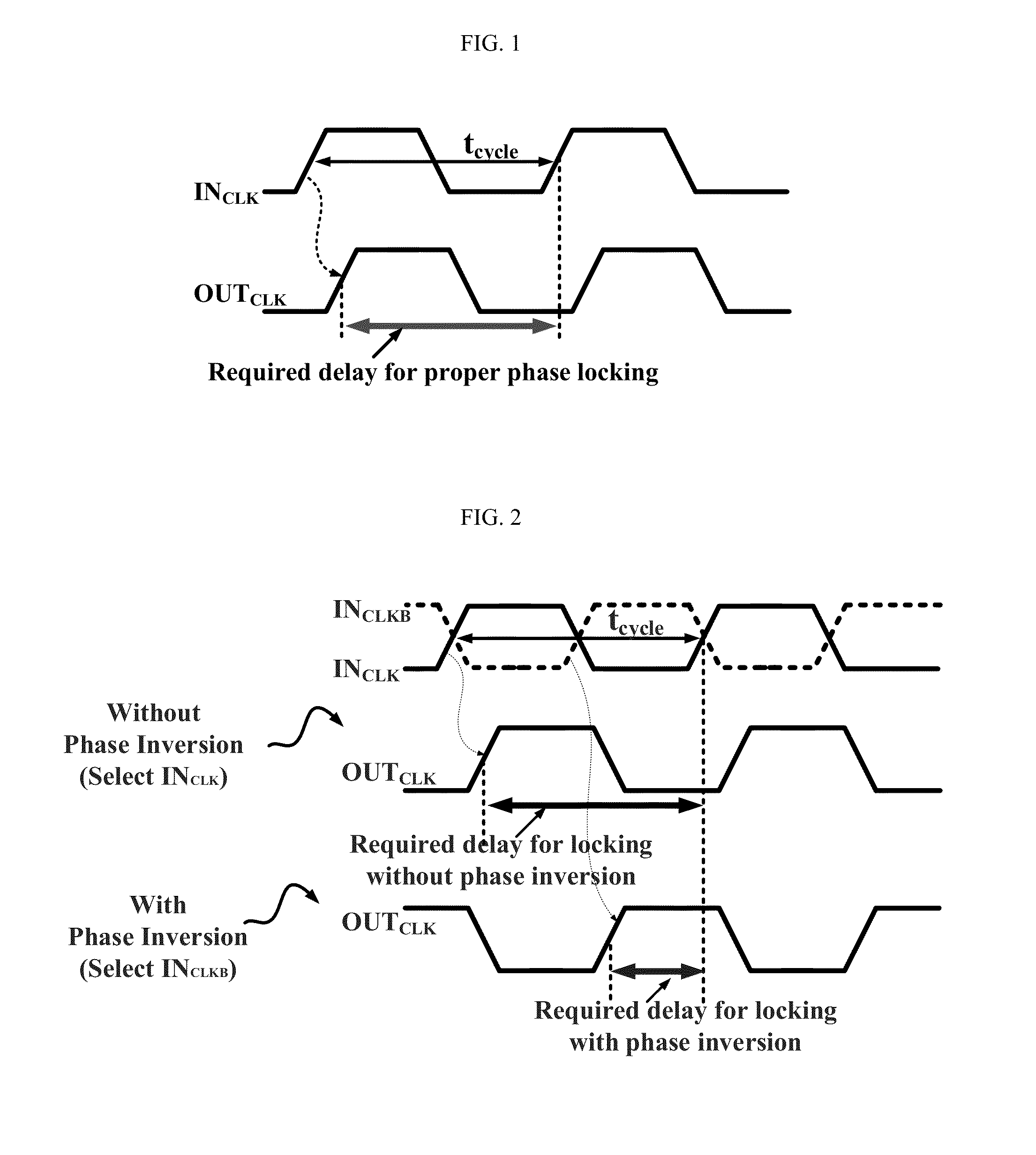
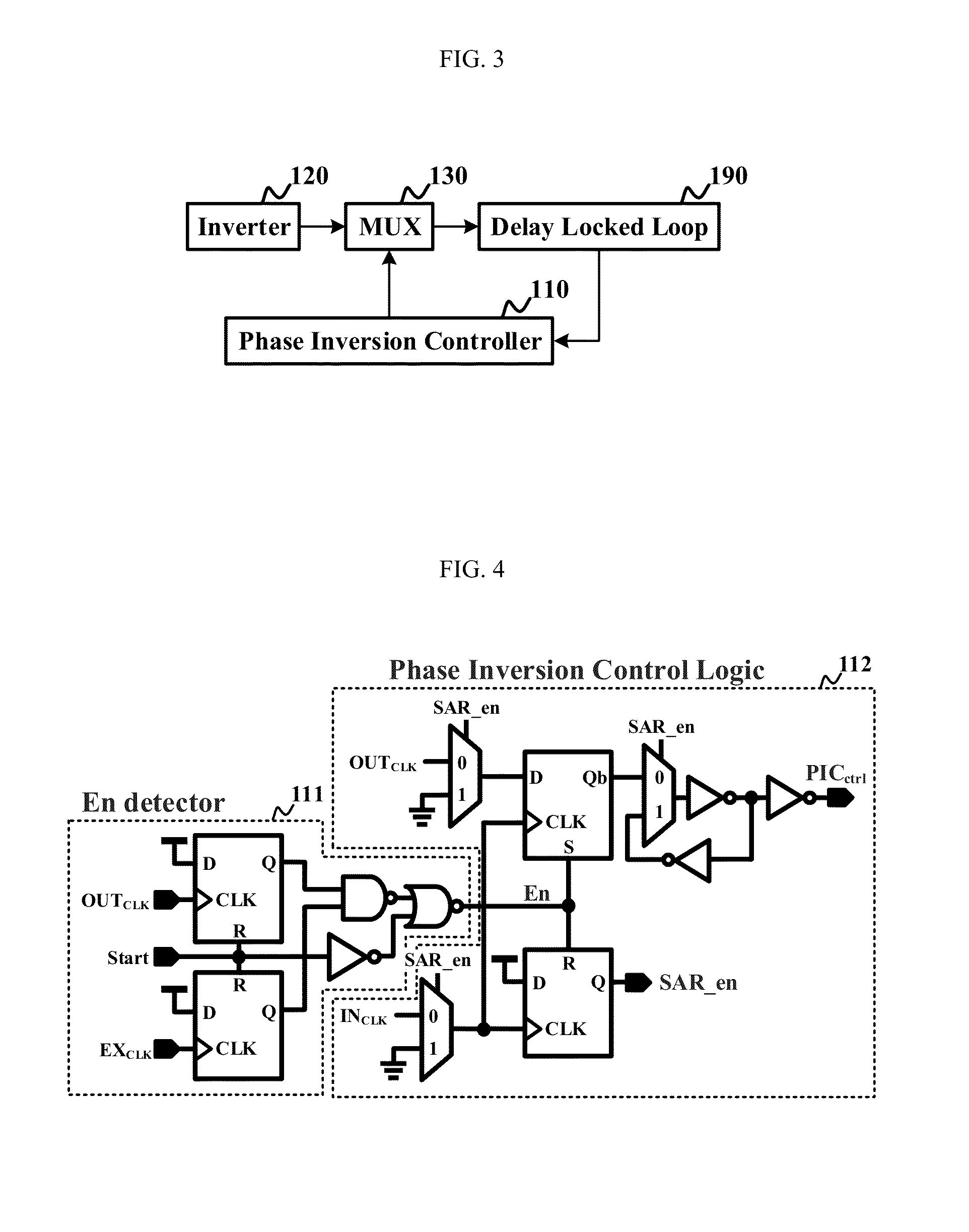
[0036]FIG. 2 is a signal diagram showing the basic principle and effects of a delay-locked loop circuit using a phase inversion locking algorithm in accordance with an embodiment of the present invention. The uppermost waveforms show an input clock signal INCLK and an inverted input clock signal INCLKB, the middle waveform shows a delay time ‘t1’ required for phase synchronization before the phase inversion locking algorithm is applied (i.e., when an input clock signal is used), and the lowermost waveform shows a delay time ‘t2’ required for phase synchronization after the phase inversion locking algorithm is applied (i.e., when an inverted input clock signal is used).

[0037]Referring to FIG. 2, if a phase error between the input clock signal INCLK and the output clock signal OUTCLK is the half cycle ‘tcycle / 2’ or more of the input clock signal an...


PUM


Abstract

Disclosed herein are a delay-locked loop circuit using a phase inversion locking algorithm and a method of controlling the same. There is provided a delay-locked loop circuit using a phase inversion locking algorithm, including a phase inversion controller configured to control whether or not to use the phase inversion locking algorithm by determining a phase error between an input clock signal and an output clock signal, an inverter configured to invert the input clock signal and output the inverted input clock signal, a multiplexer configured to receive the input clock signal and the inverted input clock signal of the inverter and output the input clock signal in response to the control signal of the phase inversion controller or the inverted input clock signal, and a delay-locked loop connected to the output terminal of the multiplexer and configured to perform phase synchronization in response to the output signal of the multiplexer.

Description

CROSS REFERENCE TO RELATED APPLICATION[0001]The present application claims the benefit of Korean Patent Application No. 10-2013-0072977 filed in the Korean Intellectual Property Office on 25 Jun. 2013, the entire contents of which are incorporated herein by reference.BACKGROUND OF THE INVENTION[0002]1. Technical Field[0003]The present invention relates to a delay-locked loop circuit using a phase inversion locking algorithm and a method of controlling the same and, more particularly, to a delay-locked loop circuit capable of implementing a wide operating frequency range, a short locking time, low power consumption, a small chip area, and improved jitter performance by reducing the number of delay units within a digitally-controlled delay line by half to a maximum extent by applying a phase inversion locking algorithm to the delay-locked loop circuit and a method of controlling the delay-locked loop circuit.[0004]2. Description of the Related Art[0005]In order to improve power consum...

Claims


Application Information

Patent Timeline
Patent Type & Authority Patents(United States)
IPC IPC(8): H03L7/08H03L7/06
CPCH03L7/0802H03L7/0814H03L7/0818H03L7/081
Inventor KIM, JONGSUNHAN, SANGWOO
Owner HONGIK UNIV IND ACAD COOP FOUND
Why Eureka
Try Eureka