Method and apparatus for down link interference cancelation between adjacent base stations in base station with reconfigurable antenna

a technology of downlink interference and reconfigurable antenna, which is applied in the field of base stations, can solve problems such as limited downlink performance, and achieve the effect of cancelling downlink interferen

Active Publication Date: 2014-10-28
SAMSUNG ELECTRONICS CO LTD
View PDF10 Cites 2 Cited by
  • Summary
  • Abstract
  • Description
  • Claims
  • Application Information

AI Technical Summary

Benefits of technology

[0008]Aspects of the present invention are to address at least the above-mentioned problems and / or disadvantages and to provide at least the advantages described below. Accordingly, an aspect of the present invention is to provide an apparatus and a method for canceling downlink interference between adjacent base stations in a base station using a reconfigurable antenna.
[0009]Another aspect of the present invention is to provide a method and an apparatus for canceling downlink interference between adjacent base stations when two or more base stations use a reconfigurable antenna with interference between adjacent base stations using the same frequency band in a mobile communication system.
[0010]In accordance with an aspect of the present invention, a method of a network device for determining a transmit antenna pattern in a mobile communication system is provided. The method includes requesting a first base station to fix a transmit antenna pattern and requesting a second base station to change a transmit antenna pattern, determining first Signal to Interference and Noise Power Ratios (SINRs) of a first mobile station and a second mobile station based on first Channel Quality Indicator (CQI) values received from the first base station and the second base station when the first base station has the fixed transmit antenna pattern and the second base station has the changed transmit antenna pattern, requesting the first base station to change the transmit antenna pattern and requesting the second base station to fix the transmit antenna pattern, determining second SINRs of the first mobile station and the second mobile station based on second CQI values received from the first base station and the second base station when the first base station has the changed transmit antenna pattern and the second base station has the fixed transmit antenna pattern, and determining a transmit antenna pattern exhibiting the best performance based on the determined first and second SINRs.
[0014]In accordance with another aspect of the present invention, a method for determining a transmit antenna pattern in a mobile communication system is provided. The method includes determining a first SINR difference of a first mobile station and a first SINR difference of a second mobile station when an antenna pattern of a first base station is fixed and an antenna pattern of a second base station is changed, determining a second SINR difference of the first mobile station and a second SINR difference of the second mobile station when the antenna pattern of the first base station is changed and the antenna pattern of the second base station is fixed, selecting an antenna pattern for each of the first and second base stations which maximizes a channel capacity based on the first and second SINR differences, and applying the selected antenna patterns to the first and second base stations.

Problems solved by technology

Disadvantageously, antennas of a fixed radiation pattern or fixed polarization exhibit optimum performance only at a particular installation location or under a particular channel condition.
When a plurality of base stations using the same frequency band is adjacent to one another in the indoor propagation environment, downlink performance is limited mainly by interference between the base stations.

Method used


Image

  • Method and apparatus for down link interference cancelation between adjacent base stations in base station with reconfigurable antenna
  • Method and apparatus for down link interference cancelation between adjacent base stations in base station with reconfigurable antenna
  • Method and apparatus for down link interference cancelation between adjacent base stations in base station with reconfigurable antenna

Examples


case 1

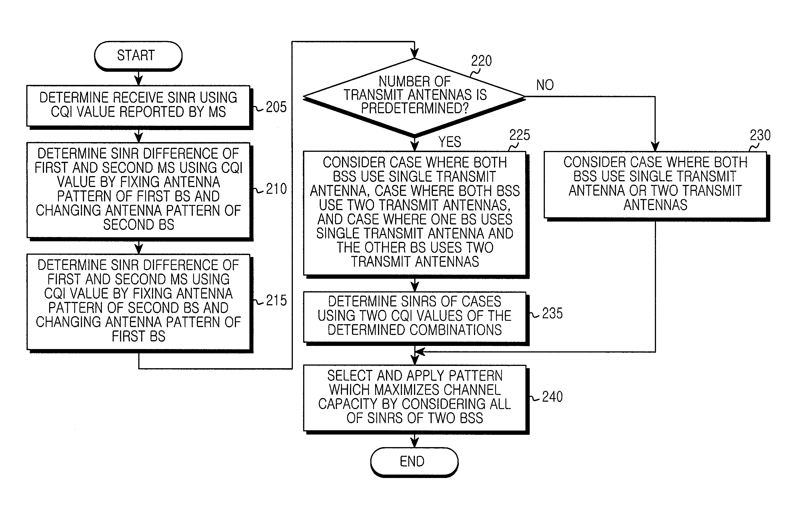
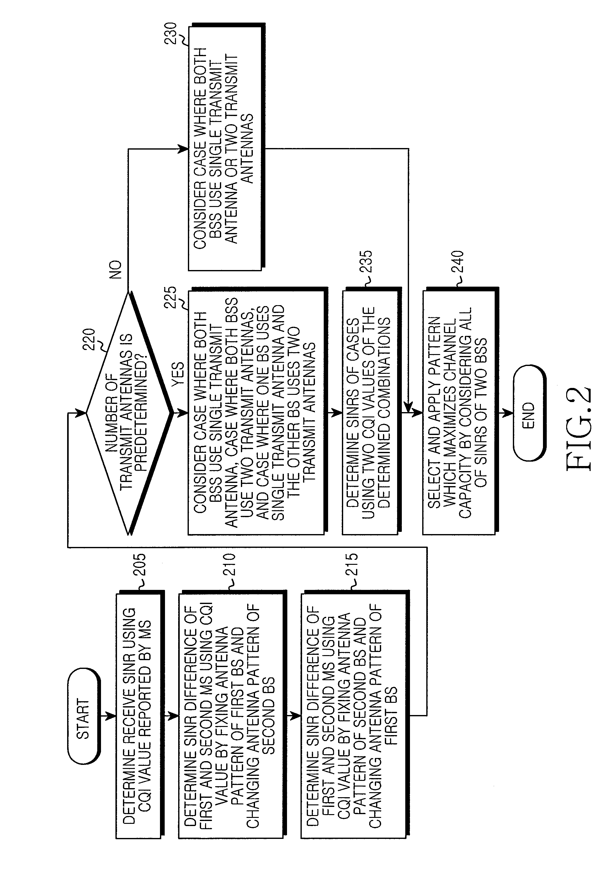
[0086 may save the scanning time by partially scanning the 24 pattern combinations and finely scanning only a small number of candidate patterns of clear difference with time using the initial partial scanning result.

[0087]The SINR of the two BSs are considered jointly. The pattern for maximizing the determination of the channel capacity of the combinations is selected and applied to each BS. The channel capacity of the two BSs is maximized based on Equation 5.

Deter min ation1=log2(1+SINR1)+log2(1+SINR2)

Dter min ation2=SINR1(dB)+SINR2(dB)  (5)

[0088]Deter min ation1 is based on the channel capacity formula of Shannon information theorem. A case that weights can be applied to Equation 5 per user may be considered and the case may be based on Equation 6.

Deter min ation3=weight1·log2(1+SINR1)+weight2·log2(1+SINR2)

Deter min ation4=weight1·SINR1(dB)+weight2·SINR2(dB)  (6)

[0089]When weight1=1 and weight2=0, only the first MS is considered and the second MS is sacrificed. The weight may var...


PUM


Abstract

A transmit antenna pattern is provided. A method for determining the transmit antenna pattern includes determining first Signal to Interference and Noise Power Ratios (SINRs) of a first mobile station and a second mobile station based on first Channel Quality Indicator (CQI) values received from a first base station and a second base station in the first operation when a transmit antenna pattern of the first base station is fixed and a transmit antenna pattern of the second base station is changed, determining second SINRs of the first mobile station and the second mobile station based on second CQI values received from the first base station and the second base station when the transmit antenna pattern of the first base station is changed and the transmit antenna pattern of the second base station is changed, and determining a transmit antenna pattern exhibiting the best performance based on the determined SINRs.

Description

PRIORITY[0001]This application claims the benefit under 35 U.S.C. §119(a) to a Korean patent application filed in the Korean Intellectual Property Office on Feb. 16, 2011, and assigned Serial No. 10-2011-0013574, the entire disclosure of which is hereby incorporated by reference.BACKGROUND OF THE INVENTION[0002]1. Field of the Invention[0003]The present invention relates to a base station. More particularly, the present invention relates to a method and an apparatus for canceling downlink interference between adjacent base stations in a base station which uses a reconfigurable antenna.[0004]2. Description of the Related Art[0005]In Wireless-Fidelity (Wi-Fi), M-Worldwide Interoperability for Microwave Access (WiMAX), and Long Term Evolution (LTE) systems, demand for compact and femto base stations to increase indoor data communication capacity is growing.[0006]In an indoor propagation environment, efficient solutions for facilitating installation of the base station or an access poin...

Claims


Application Information

Patent Timeline
Patent Type & Authority Patents(United States)
IPC IPC(8): H04W16/28H04W72/08H04W4/00
CPCH04W16/28H04W72/082H04W72/541H04B7/0413H04B7/061H04B7/0632
Inventor KIM, BYUNG-KI
Owner SAMSUNG ELECTRONICS CO LTD
Why Eureka
Try Eureka