Optical beam scanning device and image display device using the same
a scanning device and optical beam technology, applied in the direction of picture reproducers using projection devices, color television details, instruments, etc., can solve problems such as distortion in two-dimensional images displayed on screens, and achieve the effect of reducing scanning distortion
- Summary
- Abstract
- Description
- Claims
- Application Information
AI Technical Summary
Benefits of technology
Problems solved by technology
Method used
Image

Examples
first embodiment
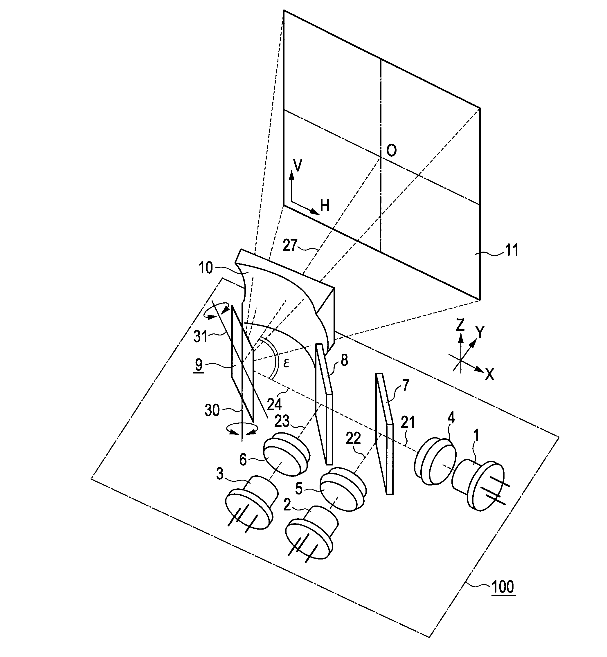
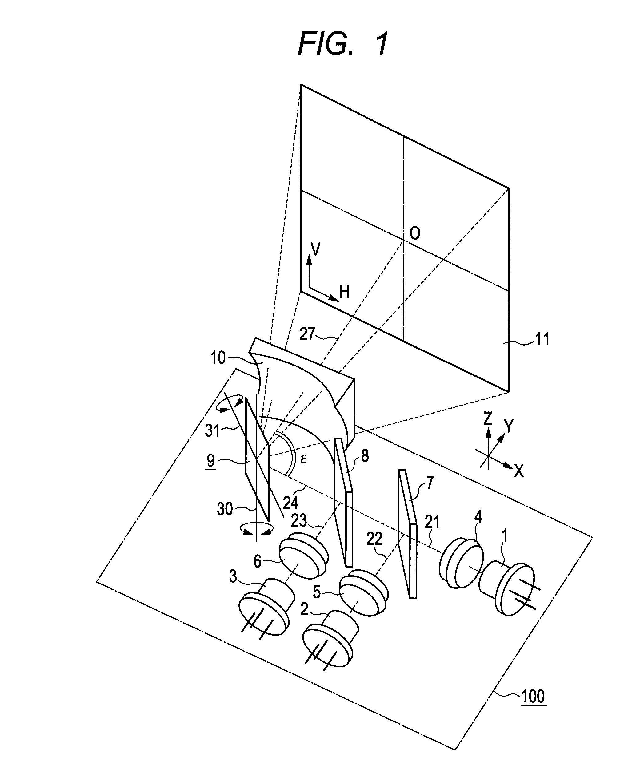
[0031]FIG. 1 is a perspective view illustrating a first embodiment of an optical beam scanning device according to the present invention. The configuration of a light beam scanning device 100 will be described.
[0032]A laser light source 1 emits a green light beam in a waveband of 520 nm, for example, and the emitted green light beam is converted into a nearly collimated light beam 21 at a collimating lens 4. A laser light source 2 emits a red light beam in a waveband of 640 nm, for example, and the emitted red light beam is converted into a nearly collimated light beam 22 at a collimating lens 5. A laser light source 3 emits a blue light beam in a waveband of 440 nm, for example, and the emitted red light beam is converted into a nearly collimated light beam 23 at a collimating lens 6. The laser light sources 1, 2, and 3 emit the light beams with intensity corresponding to signals of individual color components of image signals.
[0033]A wavelength selective mirror 7 transmits the gre...
second embodiment
[0066]FIG. 6 is a plan view illustrating a second embodiment of an optical beam scanning device according to the present invention. In the first embodiment (FIG. 1), the transmissive free-form surface lens 10 is used for a scanning distortion correcting unit. In this embodiment, a reflective free-form surface mirror 15 is used. The same components as those in FIG. 1 are designated the identical reference numbers, and the description is not repeatedly explained.
[0067]A combined light beam 24 emitted from laser light sources 1, 2, and 3 is reflected at a deflecting mirror device 9 to be a light beam 25. Suppose that an angle formed by the optical axes of the incident light beam 24 to the deflecting mirror device 9 and the emitted light beam 25 is ρ. The light beam 25 reflected at the deflecting mirror device 9 enters the free-form surface mirror 15 for correcting scanning distortion, and the light beam 25 is reflected to be a reflected light beam 27, and projected toward a screen 11. ...
third embodiment
[0076]This embodiment is different from the first embodiment in that a wedge prism 12 is disposed instead of the free-form surface lens 10 illustrated in FIG. 1 and this wedge prism 12 is an optical prism for correcting image distortion.
[0077]FIG. 8 is a diagram illustrating an optical beam scanning image display device in the case where the wedge prism 12 is disposed instead of the free-form surface lens according to the first embodiment. The same components as those in the first embodiment of the present invention illustrated in FIG. 1 are designated the identical reference numbers.
[0078]It is noted that in this embodiment, as shown in FIG. 8, in the disposed wedge prism 12 for correcting image distortion, a relative slope angle formed by an optical surface 13 on the light beam incident side and an optical surface 14 on the light beam emitting side is defend as a prism vertical angle δ, and the optical surface 14 on the light beam emitting side is disposed nearly in parallel with ...
PUM
 Abstract
Description
Claims
Application Information
 - R&D Engineer
- R&D Manager
- IP Professional
- Industry Leading Data Capabilities
- Powerful AI technology
- Patent DNA Extraction
Browse by: Latest US Patents, China's latest patents, Technical Efficacy Thesaurus, Application Domain, Technology Topic.
© 2024 PatSnap. All rights reserved.Legal|Privacy policy|Modern Slavery Act Transparency Statement|Sitemap