Retrofocus-type wide angle lens and imaging apparatus

a wide angle lens and imaging apparatus technology, applied in the field of retrofocus-type wide angle lenses and imaging apparatuses, can solve the problems of difficult to meet a request for a small f-number, and achieve the effect of reducing a spherical aberration, reducing a high-order spherical aberration and a difference in spherical aberrations

Active Publication Date: 2015-10-01
FUJIFILM CORP
View PDF1 Cites 2 Cited by
  • Summary
  • Abstract
  • Description
  • Claims
  • Application Information

AI Technical Summary

Benefits of technology

[0032]When the 3b-th lens group includes a lens having positive refractive power closest to the image side, it is possible to reduce a spherical aberration. Consequently, it is possible to easily meet a request for a small F-number.
[0033]When the 3b-th lens group includes a third-group first cemented lens having a cemented surface that is convex toward the object side and a third-group second cemented lens having a cemented surface that is convex toward the image side in this order from the object side, it is possible to reduce a high-order spherical aberration and a difference in spherical aberrations depending on wavelengths. Further, the height of an axial marginal ray at the third-group second cemented lens is lower than the height of the axial marginal ray at the third-group first cemented lens, and the height of an off-axial ray at the third-group second cemented lens is higher than the height of the off-axial ray at the third-group first cemented lens. Therefore, the effect of the third-group second cemented lens given to off-axial aberrations is greater than the effect of the third-group second cemented lens given to a spherical aberration. Hence, when the cemented surface of the third-group first cemented lens is convex toward the object side and the cemented surface of the third-group second cemented lens is convex toward the image side, it is possible to excellently correct astigmatism.
[0034]When the cemented surface of the second-group first cemented lens is convex toward the image side, a difference in spherical aberrations depending on wavelengths is less likely to be generated. When the cemented surface of the second-group second cemented lens is convex toward the object side, it is possible to excellently correct a lateral chromatic aberration.
[0035]When a stop is arranged closer to the object side than a surface closest to the image side in the 3a-th lens group, it is possible to balance the effective aperture of the lens closest to the object side, and to reduce the size of the optical system.
[0036]When focusing is performed by moving the 3b-th lens group in the direction of the optical axis, it is possible to reduce the weight of the group that moves during focusing while the optical system has a small F-number, and to suppress fluctuations of a spherical aberration and curvature of field caused by focusing.
[0037]The imaging apparatus of the present invention includes the retrofocus-type wide angle lens of the present invention. Therefore, the imaging apparatus having high performance is configurable, and excellent images are obtainable by using an imaging device.

Problems solved by technology

Although the lenses are appropriate to widen the angle of view, there is a problem that it is difficult to meet a request for a small F-number because the positive refractive power of the rear group is strong.

Method used


Image

  • Retrofocus-type wide angle lens and imaging apparatus
  • Retrofocus-type wide angle lens and imaging apparatus
  • Retrofocus-type wide angle lens and imaging apparatus

Examples


example 1

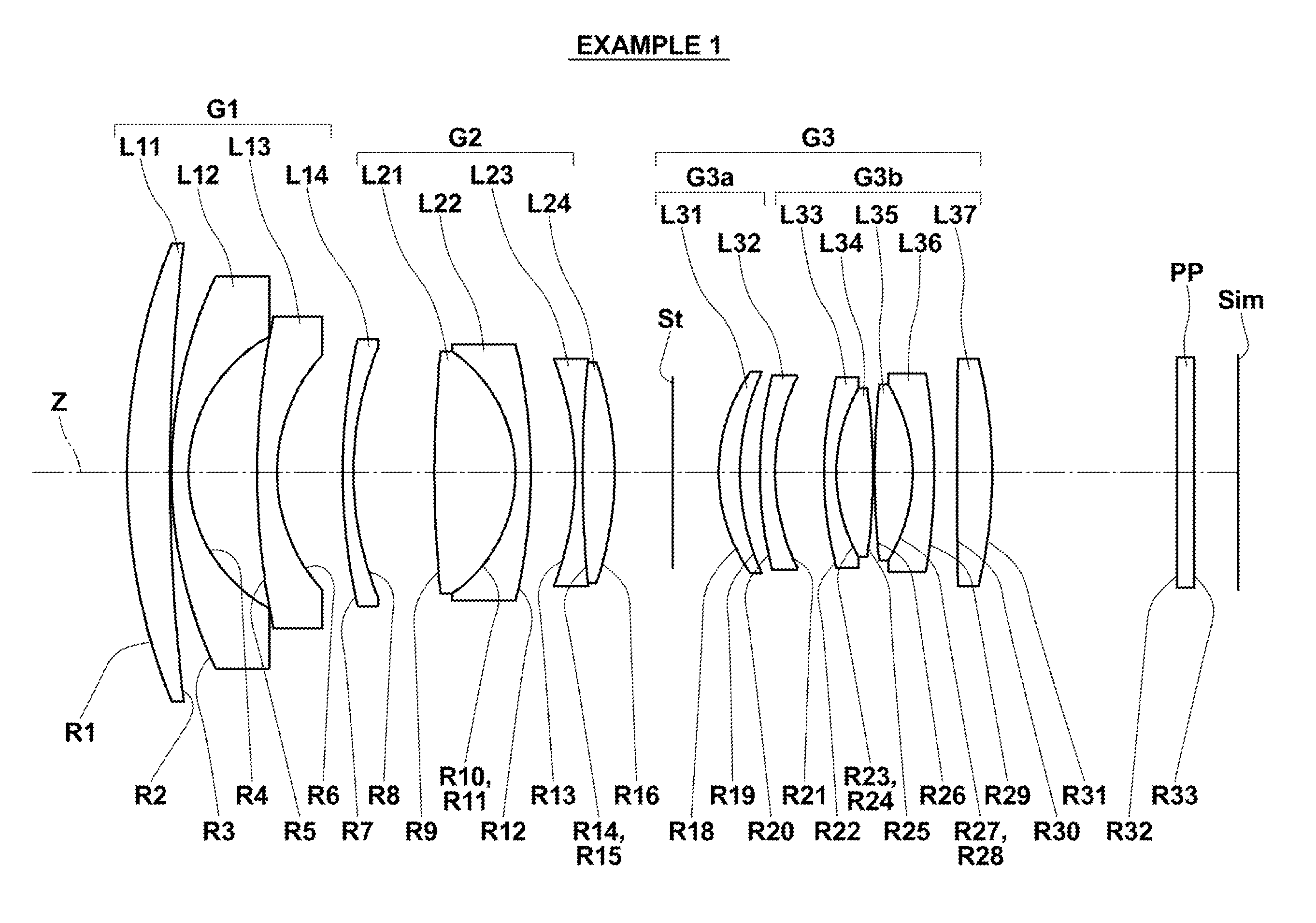
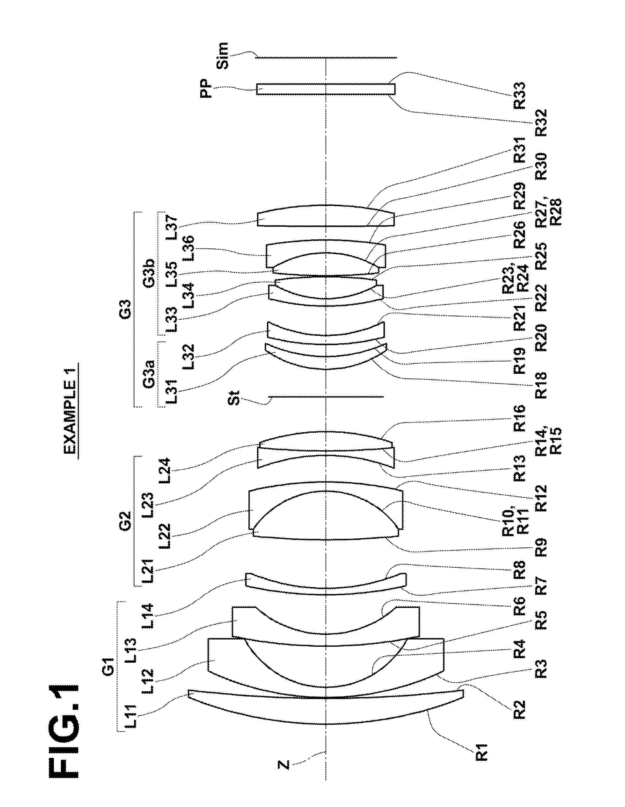
[0086]FIG. 1 illustrates the arrangement of lens groups in a retrofocus-type wide angle lens in Example 1. Since lens groups and each lens in the configuration illustrated in FIG. 1 have been described in detail already, repletion of the explanation will be omitted here unless necessary.

[0087]Table 1 shows basic lens data of the retrofocus-type wide angle lens in Example 1, and Table 2 shows other data of the retrofocus-type wide angle lens in Example 1. Similarly, Table 3 through Table 8 show basic lens data and other data of the retrofocus-type wide angle lenses in Examples 2 through 4. Next, the meanings of signs in the tables will be described by using the tables of Example 1, as an example. The meanings in Examples 2 through 4 are basically similar to Example 1. Here, Tables 1 through 8 show numerical value data normalized so that the focal length of the entire system is 1.

[0088]In the basic lens data of Table 1, a column of Si shows the surface number of an i-th (i=1, 2, 3, . ...

example 2

[0094]FIG. 3 illustrates the arrangement of lens groups in a retrofocus-type wide angle lens in Example 2. The retrofocus-type wide angle lens in Example 2 is configured almost similar to the retrofocus-type wide angle lens in Example 1, which has been described already. Table 3 shows basic lens data of the retrofocus-type wide angle lens in Example 2, and Table 4 shows other data of the retrofocus-type wide angle lens in Example 2. FIG. 7, Sections A through D are diagrams illustrating various aberrations of the retrofocus-type wide angle lens in Example 2.

TABLE 3EXAMPLE 2•BASIC LENS DATASiRiDindjvdj13.90250.251.7725049.60210.84850.0132.62630.071.6180063.3340.98820.5454.78210.071.8051825.4261.17880.3974.79360.071.4874970.2382.02500.5697.26810.511.9036631.3210−0.96750.001.5600237.6511−0.96750.071.8466123.7812−3.73640.2413−1.98990.051.6134044.271411.21360.001.5600237.651511.21360.201.7847026.2916−2.08350.4217(STOP)∞0.19181.19660.131.5182358.90191.85360.35202.20690.071.4874970.23211.2...

example 3

[0095]FIG. 4 illustrates the arrangement of lens groups in a retrofocus-type wide angle lens in Example 3. The retrofocus-type wide angle lens in Example 3 is configured almost similar to the retrofocus-type wide angle lens in Example 1, which has been described already. However, Example 3 differs from Example 1 in that aperture stop St is arranged between positive meniscus lens L31 and negative meniscus lens L32 in 3a-th lens group G3a.

[0096]Table 5 shows basic lens data of the retrofocus-type wide angle lens in Example 3, and Table 6 shows other data of the retrofocus-type wide angle lens in Example 3. FIG. 8, Sections A through D are diagrams illustrating various aberrations of the retrofocus-type wide angle lens in Example 3.

TABLE 5EXAMPLE 3•BASIC LENS DATASiRiDindjvdj13.75060.311.7725049.60210.23860.0231.85270.071.6180063.3341.04310.5456.02260.071.8466123.7861.01480.3677.61220.121.4874970.2382.13370.6797.91180.461.9036631.3210−0.95290.001.5600237.6511−0.95290.071.8466123.7812−...


PUM


Abstract

A retrofocus-type wide-angle lens consists of a negative first lens-group, a positive second lens-group, and a positive third lens-group in this order from an object-side. The first lens-group consists of a positive meniscus-lens with its convex surface facing the object-side and three negative meniscus-lenses with their convex surfaces facing the object-side in this order from the object-side. The second lens-group includes two cemented lenses, and a lens closest to an image-side in the second lens-group is one of the at least two cemented lenses. The third lens-group consists of a 3a-th lens-group, which consists of a positive meniscus-lens with its convex surface facing the object-side and a negative meniscus-lens with its convex surface facing the object-side, and a 3b-th lens-group, which includes at least two cemented lenses and has positive refractive power as a whole, in this order from the object-side.

Description

CROSS-REFERENCE TO RELATED APPLICATIONS[0001]This application is a Continuation of PCT International Application No. PCT / JP2013 / 006937 filed on Nov. 26, 2013, which claims priority under 35 U.S.C §119(a) to Japanese Patent Application No. 2012-274475 filed on Dec. 17, 2012. Each of the above applications is hereby expressly incorporated by reference, in its entirety, into the present application.BACKGROUND OF THE INVENTION[0002]1. Field of the Invention[0003]The present invention relates to a retrofocus-type wide angle lens and an imaging apparatus on which this lens has been mounted. In particular, the present invention relates to a retrofocus-type wide angle lens appropriate for use in a middle-size single-lens reflex camera and an imaging apparatus on which this retrofocus-type wide angle lens has been mounted.[0004]2. Description of the Related Art[0005]Generally, a sufficient length of backfocus needs to be secured in a wide angle lens for a single-lens reflex camera. Therefore...

Claims


Application Information

Patent Timeline
Patent Type & Authority Applications(United States)
IPC IPC(8): G02B13/04G02B9/12
CPCG02B9/12G02B13/04G02B13/06
Inventor SHIMADA, YASUTAKA
Owner FUJIFILM CORP
Why Eureka
Try Eureka