
Large visual field optical imaging method for guided missile detection and identification and system thereof

An optical imaging system and optical imaging technology, applied in the field of optical systems, can solve problems affecting imaging performance, non-imaging light, chromatic aberration, etc., and achieve the effects of reducing astigmatism, reducing stray light, and reducing aberrations

Inactive Publication Date: 2014-01-15
SUZHOU UNIV
View PDF0 Cites 9 Cited by
  • Summary
  • Abstract
  • Description
  • Claims
  • Application Information

AI Technical Summary

Problems solved by technology

Broadband and large field of view will cause chromatic aberration and distortion respectively, and large field of view will also produce serious non-imaging light, which will affect imaging performance

Method used


Image

  • Large visual field optical imaging method for guided missile detection and identification and system thereof
  • Large visual field optical imaging method for guided missile detection and identification and system thereof
  • Large visual field optical imaging method for guided missile detection and identification and system thereof

Examples


Embodiment 1

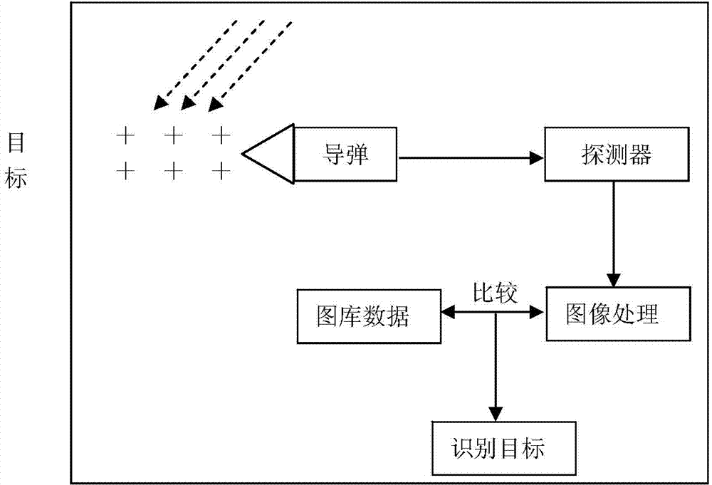
[0025] The technical solution of this embodiment is to provide a large field of view optical imaging system for missile detection and identification, its working band is 0.72μm~1.0μm, the system F number is F / #=3.0, and the full field of view angle is 17.5 Spend.

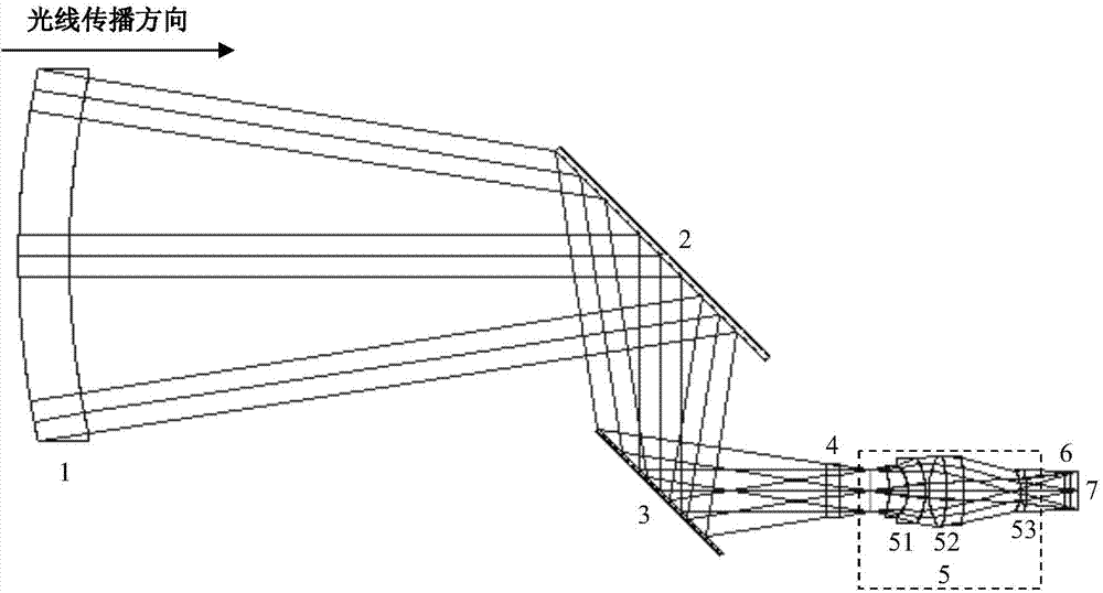
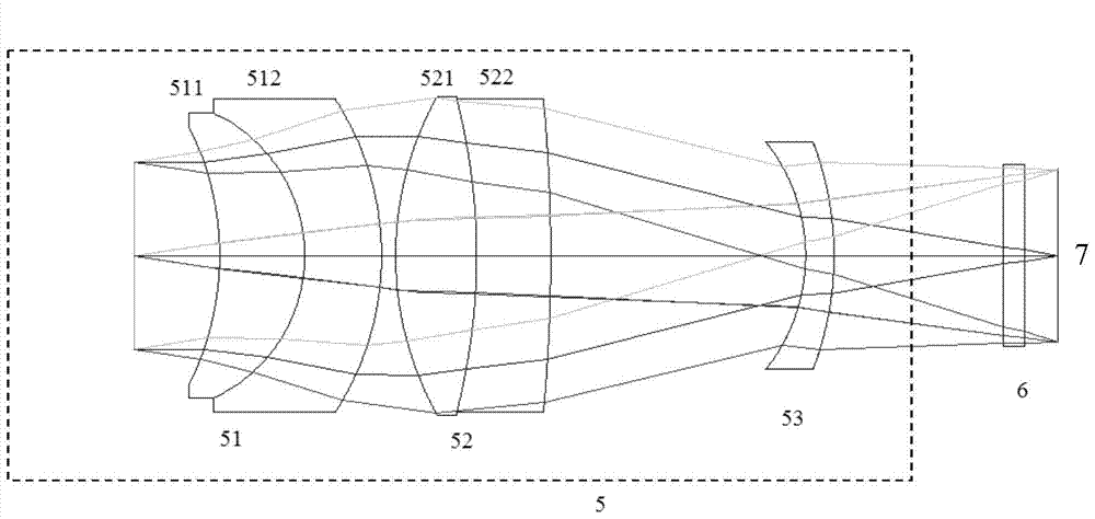
[0026] See attached figure 2 with 3 , which are the optical path diagram of the large field of view optical imaging system for missile detection and identification provided in this embodiment and the structural schematic diagram of the improved Petzwan objective lens; figure 2It can be seen that the imaging optical system is composed of two plane mirrors and seven lenses, along the incident direction of light, there are meniscus spherical negative lens 1, folded plane mirror 2, folded plane mirror 3, optical filter Sheet 4, the first doublet lens group 51, the second doublet lens group 52 and a meniscus spherical lens 53 of the improved Petzwan structure objective lens 5 constitute, doublet lens group 51 is made...

Embodiment 2

[0040] In this embodiment, the working waveband is 0.72 μm to 1.0 μm, the system F-number is F / #=3.0, and the full field of view is 17.5 degrees. For the optical system structure and imaging optical path, please refer to the attached figure 2 .

[0041] The remaining parameters of the optical imaging system are as follows: the focal length of the optical system is 20 mm, the meniscus spherical negative lens 1, the first doublet positive lens 511, the first doublet negative lens 512, the second doublet positive lens 521, The radii of curvature of the second double glued negative lens 522 and the meniscus spherical lens 53 are respectively 139.55mm, 131.05mm, -11.02mm, -5.35mm, -10.03mm, 11.54mm, -22.17mm, -58.95mm, -6.34mm, -11.35mm; along the light incident direction, the thickness of each lens is 8.50mm, 2.11mm, 2.97mm, 2.73mm, 2.81mm, 2.62mm; the refractive index of each lens material is 1.53, 1.55, 1.76 , 1.62, 1.74, 1.76. The large field of view optical system is suitab...


PUM


Abstract

The invention relates to a large visual field optical imaging method for guided missile detection and identification and a system thereof. The optical system is carried by a guided missile and used for target detection and identification, and comprises an optical glass ball cover, two folded plane reflectors, a band-pass filter, an electrical control diaphragm and an improved Pittsburgh Wan structural objective lens, wherein the improved Pittsburgh Wan structural objective lens is formed by two doublet lens groups and a meniscus lens. According to the invention, the two folded plane reflectors are adopted by the system, so that the system length is reduced, the mounting and adjustment are easy, and the stability is excellent; the requirement for the guided missile pre-reserved space is met while the veiling glare coefficient can be effectively reduced; the system is operated within a wide wave band range and a wide temperature range, chromatic aberration and optical aberration relevant to a visual field are reduced through selecting reasonable glass materials; the system adopts a refraction and reflection type optical structure, is simple and compact, is applicable to wider near-infrared band, has an adaptive temperature range, and has the characteristics of small chromatic aberration, strong athermalization capability, small distortion, excellent imaging performance and the like.

Description

technical field [0001] The present invention relates to an optical system mounted on a missile, in particular to an optical system that adopts a catadioptric structure, works in the near-infrared band, has a large field of view, a large aperture, has good non-imaging light suppression performance, and is used for target tracking and recognition. Imaging method and system thereof. Background technique [0002] The high-performance optical system for large field of view and low stray light target acquisition, tracking and identification is an important component to ensure the accuracy of target acquisition and improve the efficiency of detection and identification of aircraft and spacecraft. With the expansion of the detection field, due to the limitation of the working band and strong non-imaging light interference, it is difficult for ordinary optical systems to simultaneously capture, accurately track and quickly identify weak targets in the near-infrared band. [0003] Se...

Claims


Application Information

Patent Timeline
Patent Type & Authority Applications(China)
IPC IPC(8): G02B17/08G02B27/00G01J5/08
Inventor 季轶群石荣宝周建康王岩
Owner SUZHOU UNIV
Learn More