Objective lens system for microscope

a technology of objective lens and microscope, which is applied in the field of microscope lenses, can solve the problems of unsuitability of objective lens systems, small numerical apertures, and long working distances, and achieve the effect of high resolution

Active Publication Date: 2007-01-02
EVIDENT CORP
View PDF1 Cites 9 Cited by
  • Summary
  • Abstract
  • Description
  • Claims
  • Application Information

AI Technical Summary

Benefits of technology

[0027]Furthermore, the cemented lens component of the second lens unit is disposed in a rear unit of the objective lens system, or at a location through which rays pass gently. Since the cemented lens component comprises in the second lens unit is disposed at the location through which the rays pass gently, it is possible to configure this lens component so as to reduce influences on spherical aberration, astigmatism and coma, and have a function to correct mainly the longitudinal chromatic aberration.
[0033]When the condition (6) is satisfied, it is possible to favorably correct chromatic aberration of the d-line, C-line and F-line. Furthermore, a glass material which has an Abbe's number larger than 75 exhibits high anomalous dispersion for the g-line and can favorably correct chromatic aberration of the g-line.
[0035]Then, the cemented lens component which is comprises in the second lens unit and has the above described composition makes it possible to correct chromatic aberration in the visible region and an infrared region. The condition (2) has been adopted for correcting chromatic aberration in the visible region.
[0071]If νd,ave(G2p)−νd,ave(G2n) has a value smaller than a lower limit of 25 of the condition (11), a difference will be small between Abbe's numbers of a positive lens element and a negative lens element, thereby making it difficult to correct chromatic aberration in the visible region. When the condition (12) is satisfied, it is possible to favorably correct chromatic aberration of the d-line, C-line and F-line. Furthermore, a glass material which has an Abbe's number larger than 75 exhibits a high anomalous dispersion property for the g-line and is capable of favorably correcting chromatic aberration also of the g-line.
[0076]An optical microscope or an optical observation apparatus which is equipped with the above described objective lens system according to the present invention permits observing bright images of specimens with high resolution, thereby being effective for observation of cells and others.

Problems solved by technology

However, these objective lens systems which are configured to observe the semiconductor integrated circuits and the liquid crystal panels have long working distances and therefore small numerical apertures.
Accordingly, these objective lens systems are unsuitable for use as objective lens systems for observation of cells, proteins, DNAs and the like which must be observed as highly resolved images and bright images.

Method used


Image

  • Objective lens system for microscope
  • Objective lens system for microscope
  • Objective lens system for microscope

Examples


first embodiment

[0096]The first embodiment has numerical data listed below:

[0097]

f = 45, β = 4x, NA = 0.16, field number = 26.5,WD = 13.327r1 = 23.5100d1 = 3.3114n1 = 1.51633ν1 = 64.14r2 = −18.0816d2 = 1.1909r3 = 11.9099d3 = 8.3841n2 = 1.49700ν2 = 81.54r4 = −11.4327d4 = 1.4037n3 = 1.74100ν3 = 52.64r5 = 7.6802d5 = 4.9712r6 = −4.8583d6 = 1.8582n4 = 1.77250ν4 = 49.60r7 = 511.8307d7 = 3.2971n5 = 1.43875ν5 = 94.93r8 = −7.5362d8 = 0.2307r9 = −269.1995d9 = 4.7695n6 = 1.49700ν6 = 81.54r10 = −11.3589d10 = 0.3500r11 = −56.7065d11 = 1.2469n7 = 1.48749ν7 = 70.23r12 = 15.5159d12 = 4.2171n8 = 1.49700ν8 = 81.54r13 = −24.9502νd(L1p) = 81.54νd(L1n) = 52.64νd(L2p) = 81.54νd(L2n) = 70.23θCt(L2p) = 0.8258θCt(L2n) = 0.8924f(L2) = 79.799f = 45(1) νd(L1p) −νd(L1n) = 28.9(2) νd(L2p) = 81.54(3) {θCt(L2p) −θCt(L2n)} / {νd(L2p) −νd(L2n)} = −0.0059(4) f = 45(5) |f(L2) / f| = 1.77(6) νd(L1p) = 81.54

wherein the reference symbols r1, r2, . . . represent radii of curvature on surfaces of respective lens elements, the reference symbol...

second embodiment

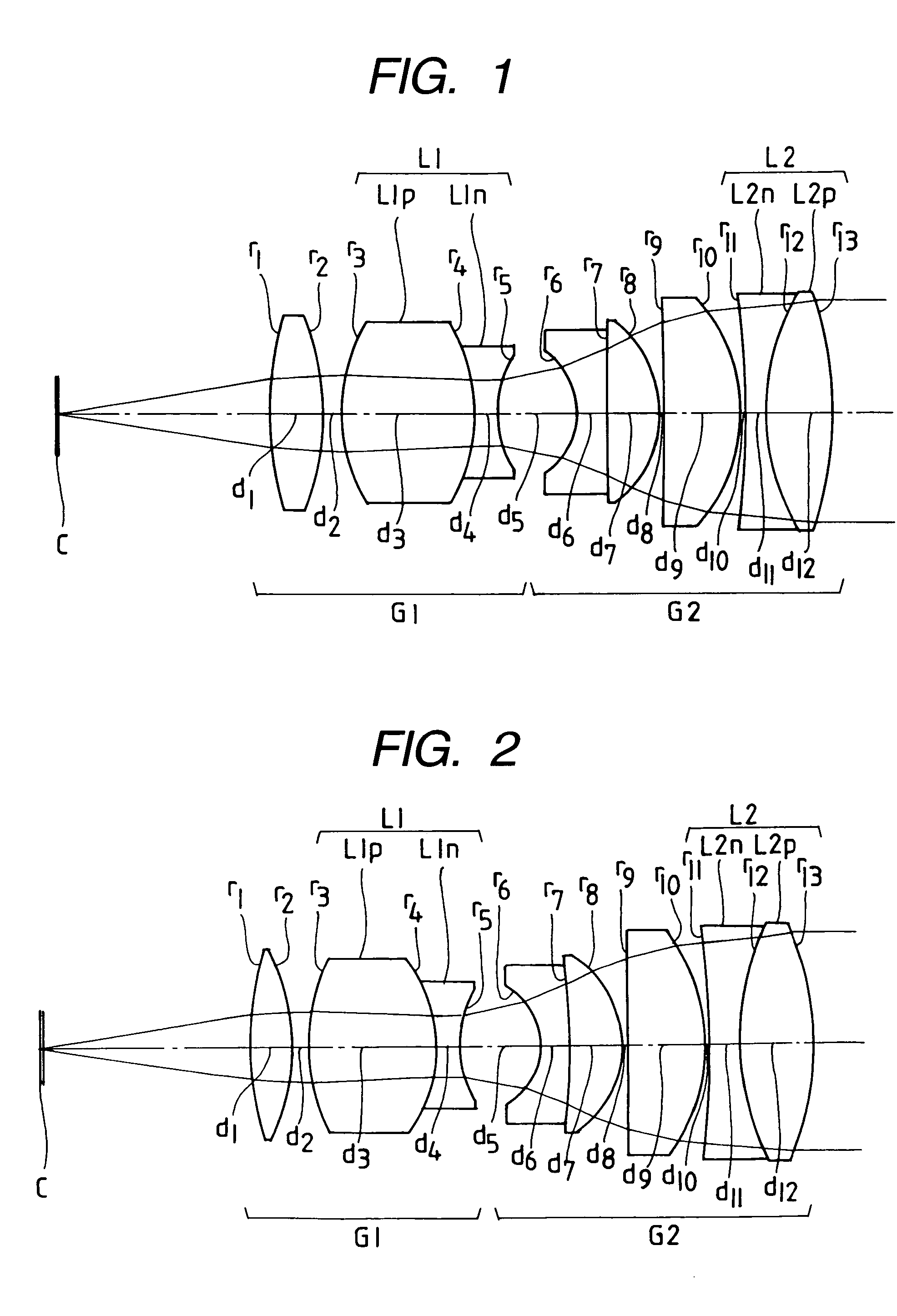
[0099]An objective lens system has the first composition shown in FIG. 2. Speaking concretely, this objective lens system consists of a first lens unit G1 and a second lens unit G2. The first lens unit G1 consists, in order from the object side, of a positive lens element (r1 or r2), and a cemented lens component L1 (r3 to r5) which consists of a positive lens element Lp1 (r3 to r4) and a negative lens element L1n (r4 to r5) having a concave surface on the image side. Furthermore, the second lens unit G2 consists, in order from the object side, of a cemented lens component (r6 to r8) which consists of a negative lens element (r6 to r7) and a positive lens element (r7 to r8), a positive lens element (r9 to r10), and a cemented lens component L2 (r11 to r13) which consists of a negative lens element L2n (r11 to r12) having a concave surface on the object side and a positive lens element L2p (r12 to r13).

[0100]The second embodiment also uses a glass material which is excellent in tran...

third embodiment

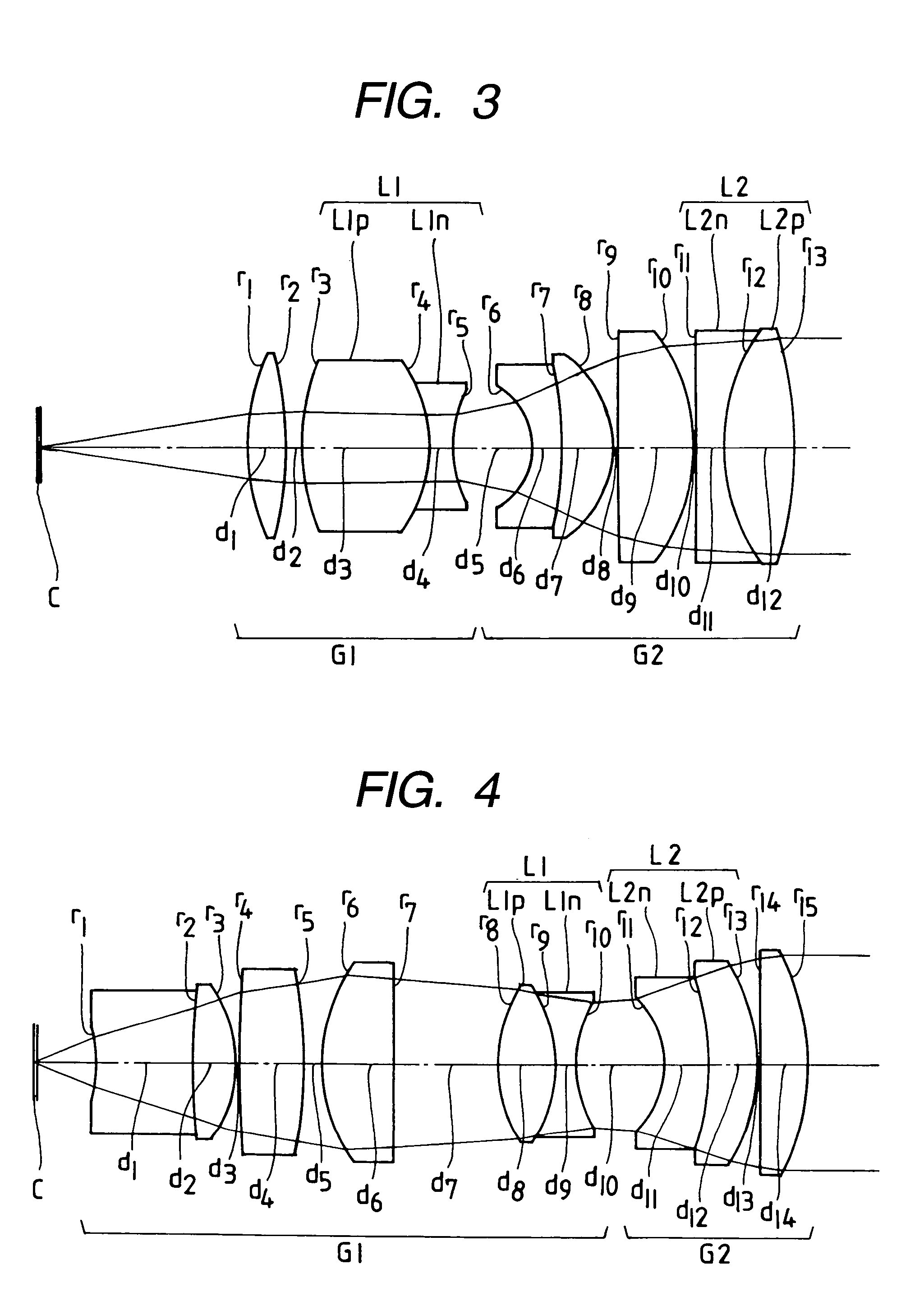
[0103]A third embodiment provides an objective lens system for microscope which has the first composition shown in FIG. 3, and consists of a first lens unit G1 and a second lens unit G2.

[0104]In the third embodiment, the first lens unit G1 consists, consists, in order from the object side, of a positive lens element (r1 to r2), and a cemented lens component L1 (r3 to r5) which consists of a positive lens element L1p (r3 to r4) and a negative lens element L1n (r4 to r5) having a concave surface on the image side. Furthermore, The second lens unit consists, in order from the object side, of a cemented lens component (r6 to r8) which consist of a negative lens element (r6 to r7) and a positive lens element (r7 to r8), a positive lens element (r9 to r10), and a cemented lens component L2 (r11 to r13) which consists of a negative lens element L2n (r11 to r12) having a planar surface on the object side and a positive lens element L2p (r12 to r13).

[0105]The third embodiment has numerical d...


PUM


Abstract

An objective lens system for microscope which comprises first and second lens units or first through fourth lens units, and in which the second or third lens unit has a function to correct chromatic aberration within a range from a visible region to a near infrared region and aberrations are favorably corrected within the range from the visible region to the near infrared region.

Description

BACKGROUND OF THE INVENTION[0001]a) Field of the Invention[0002]The present invention relates to a lens system for microscope, and more specifically an apochromat objective lens system for microscope which has a magnification on the order of 4× to 40× and aberrations favorably corrected within a range from a visible region to a near infrared region.[0003]b) Description of the Prior Art[0004]In markets of research fields associated with biology, there have recently been posed requirements such as those which are described below.[0005]First, in a market of a fluorescence observation method by which fluorescence has been observed in a near infrared region utilizing pigments which emit fluorescence having wavelengths longer than those conventionally used, there are requirements for optical systems which exhibit favorably imaging performance in the near infrared region.[0006]Furthermore, in a field of a near infrared DIC observation method which has recently been utilized, there are requ...

Claims


Application Information

Patent Timeline
Patent Type & Authority Patents(United States)
IPC IPC(8): G02B21/02
CPCG02B21/02
Inventor SAKAKURA, MASAHIROFUJIMOTO, YASUSHI
Owner EVIDENT CORP
Why Eureka
Try Eureka