Unlock instant, AI-driven research and patent intelligence for your innovation.

Variable magnification optical system and imaging apparatus

a magnification optical system and variable magnification technology, applied in the field of variable magnification optical systems and imaging apparatuses, can solve the problems of poor lateral chromatic aberration, and poor lateral chromatic aberration, and achieve excellent correction of lateral chromatic aberration, high image quality, and excellent lateral chromatic aberration

Inactive Publication Date: 2014-05-29
FUJIFILM CORP
View PDF1 Cites 3 Cited by
  • Summary
  • Abstract
  • Description
  • Claims
  • Application Information

AI Technical Summary

Benefits of technology

The present invention provides a variable magnification optical system that can efficiently correct a lateral chromatic aberration when an extender has been inserted. The system includes a relay lens group and an extender lens group, which extends a focal length towards a telephoto side without changing an image formation position. The extender lens group consists of a first lens group and a second lens group, with the second lens group being a cemented lens consisting of convex meniscus lens, biconcave lens, and convex meniscus lens. The system can provide high-quality images with corrected lateral chromatic aberrations.

Problems solved by technology

However, a lateral chromatic aberration is not improved.
Further, the lens has a known structure in which the condition of the lateral chromatic aberration is not deemed excellent.
Therefore, the lateral chromatic aberration is not improved.
Therefore, the lateral chromatic aberration is not sufficiently managed.

Method used


Image

  • Variable magnification optical system and imaging apparatus
  • Variable magnification optical system and imaging apparatus
  • Variable magnification optical system and imaging apparatus

Examples


Embodiment Construction

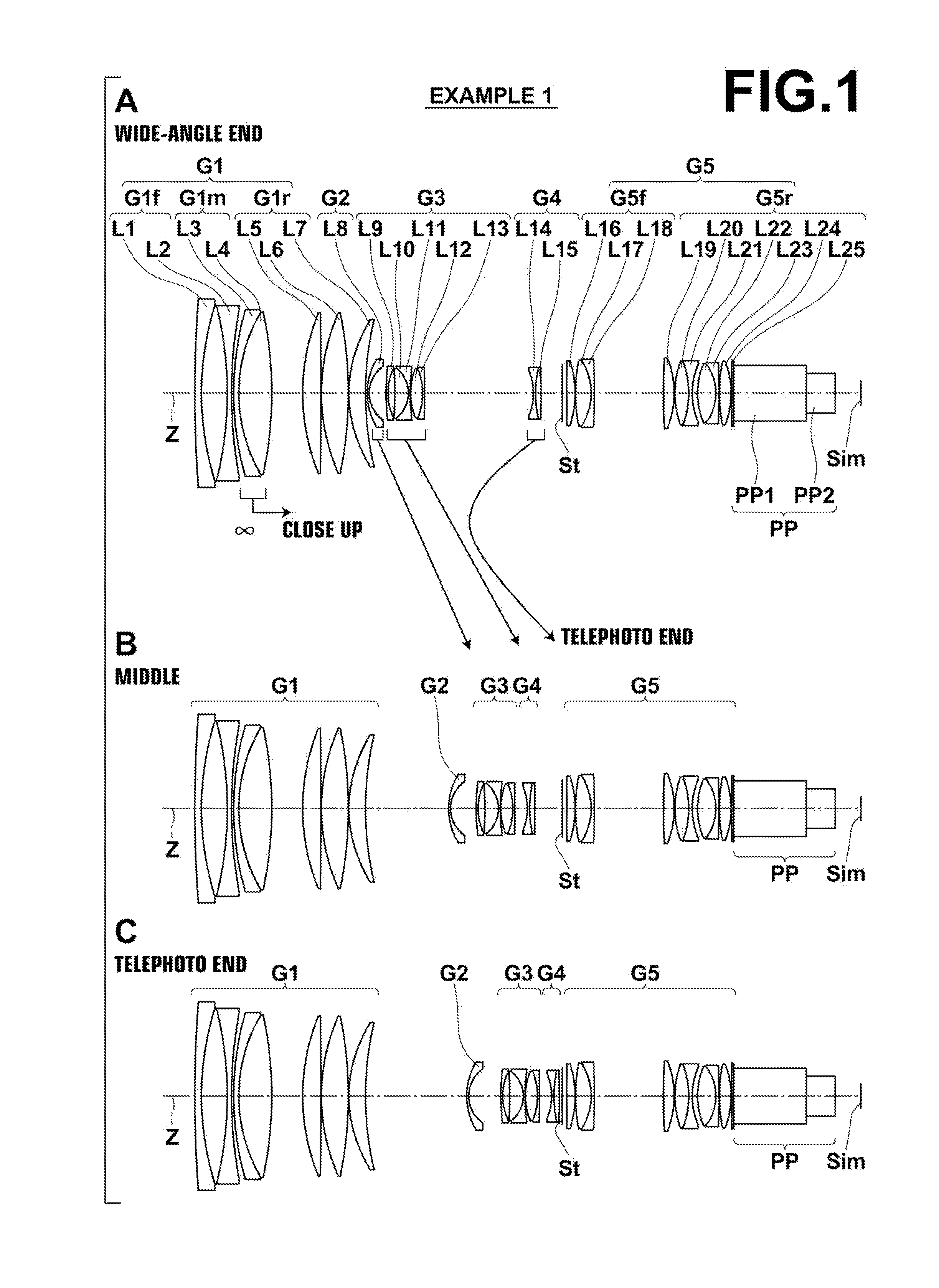
) before an extender lens group is inserted;

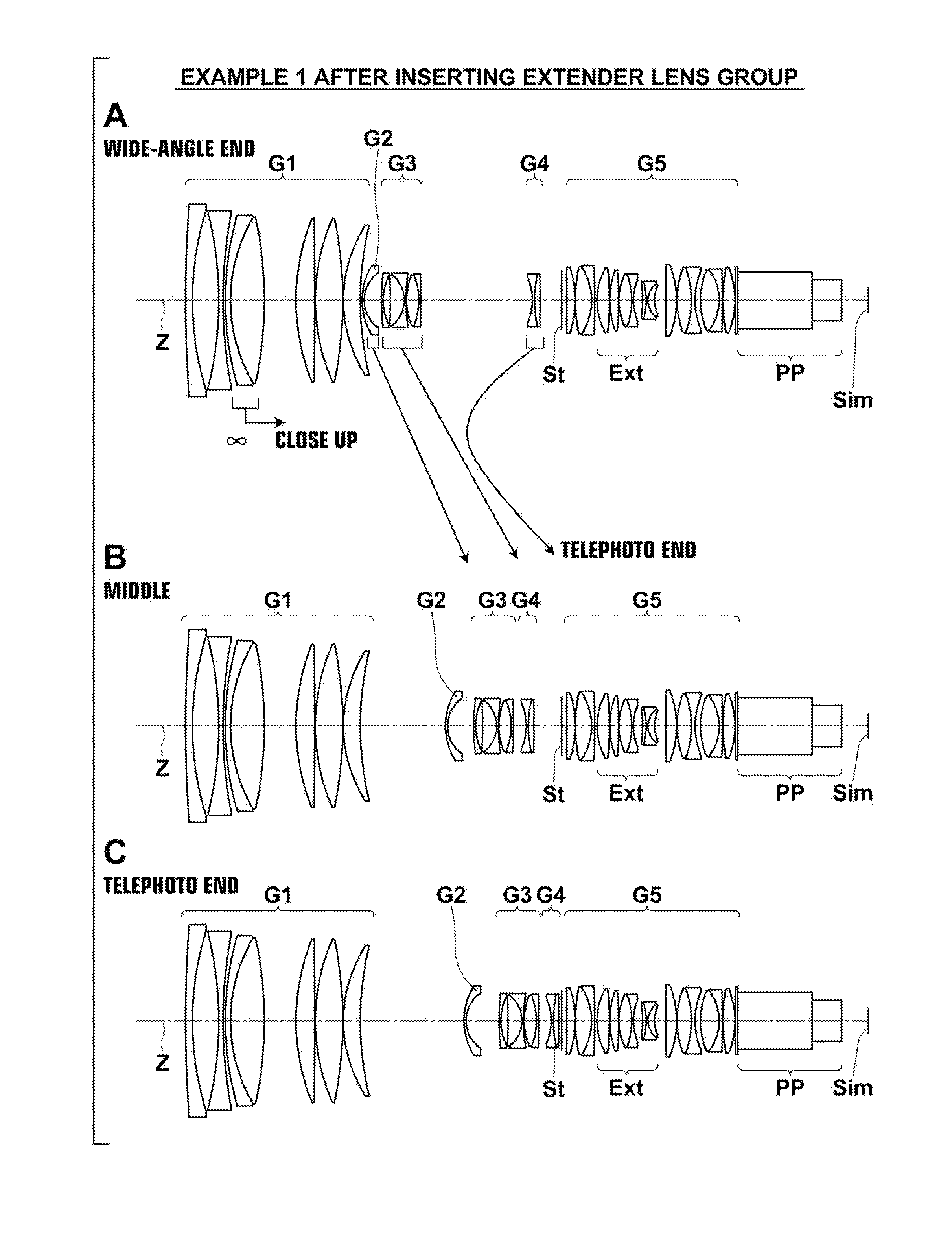
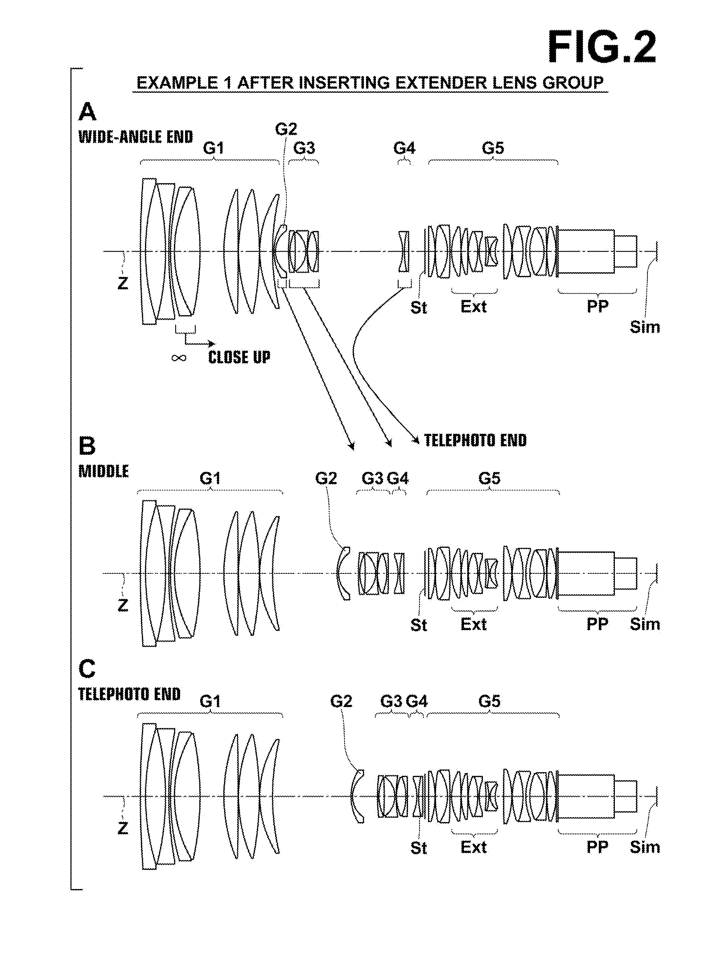
[0028]FIG. 2, Sections A through C are cross sections illustrating the lens structure of the variable magnification optical system according to an embodiment of the present invention (also Example 1) after the extender lens group is inserted;

[0029]FIG. 3 is a cross section illustrating the lens structure of the extender lens group in the variable magnification optical system according to an embodiment of the present invention (also Example 1);

[0030]FIG. 4, Sections A through C are cross sections illustrating the lens structure of a variable magnification optical system in Example 2 of the present invention before an extender lens group is inserted;

[0031]FIG. 5, Sections A through C are cross sections illustrating the lens structure of the variable magnification optical system in Example 2 of the present invention after the extender lens group is inserted;

[0032]FIG. 6 is a cross section illustrating the lens structure of the extender lens g...


PUM


Abstract

A variable magnification optical system includes a relay lens group (a fifth lens group) substantially consisting of a relay front group and a relay rear group with a predetermined air space therebetween, and which is fixed during magnification change and has image formation action, and an extender lens group insertably and detachably arranged between the relay front group and the relay rear group, and which extends a focal length toward a telephoto side without changing an image formation position. The extender lens group substantially consists of a first lens group having positive refractive power and a second lens group having negative refractive power in this order from an object side. The second lens group is a cemented lens substantially consisting of a convex meniscus lens, a biconcave lens and a convex meniscus lens in this order from the object side.

Description

CROSS REFERENCE TO RELATED APPLICATIONS[0001]This application is a continuation of PCT / JP2012 / 005444 filed on Aug. 29, 2012, which claims foreign priority to Japanese Application No. 2011-187421 filed on Aug. 30, 2011. The entire contents of each of the above applications are hereby incorporated by reference.BACKGROUND OF THE INVENTION[0002]1. Field of the Invention[0003]The present invention relates to a variable magnification optical system and an imaging apparatus. In particular, the present invention relates to a variable magnification optical system usable in a video camera, an electronic still camera and the like, and appropriate especially for a surveillance camera, and also to an imaging apparatus including the variable magnification optical system.[0004]2. Description of the Related Art[0005]Conventionally, variable magnification optical systems for CCTV (Closed-circuit Television) were developed, as optical systems for imaging apparatuses, such as a video camera, an electr...

Claims


Application Information

Patent Timeline
Patent Type & Authority Applications(United States)
IPC IPC(8): G02B15/14
CPCG02B15/10G02B15/17G02B15/20G02B27/005G02B15/144101G02B15/145117G02B13/18
Inventor IKEDA, SHINKICHISHIMADA, YASUTAKA
Owner FUJIFILM CORP