Method for estimating leaks from ventilator circuits

a ventilator circuit and leakage estimation technology, applied in the field of ventilators, can solve the problems of air leaking from the ventilator circuit, leakage of different components of the tubing, and increase the anatomical size of the leakag

Inactive Publication Date: 2014-12-16
YRT
View PDF7 Cites 7 Cited by
  • Summary
  • Abstract
  • Description
  • Claims
  • Application Information

AI Technical Summary

Problems solved by technology

In both invasive and non-invasive ventilation, the seal is at times imperfect resulting in air leaking from the ventilator circuit.
In addition to these leaks at the interface, leaks can potentially arise from loose connections between different components of the tubing or defective tubing and, in the case of NIV, from deliberate leaks inserted in the tubing to act as a conduit for carbon dioxide removal.
With mask leaks, leak flow may increase linearly with flow or may increase disproportionately as pressure increases because the mask lifts away from the face, increasing the anatomical size of the leak.
Thus, in practice, the relation between instantaneous pressure and leak flow is highly unpredictable.
This could result in malfunction of the ventilator, particularly with respect to the times the ventilator is required to increase or decrease circuit pressure (triggering and cycling-off).
Determination of the instantaneous relation between circuit pressure and leak has been problematic for the following reason.
While this is true with built-in leaks, such as those inserted in the tubing during NIV, it is not true for unintentional leaks at the interface.
Although this may accurately reflect the leak flow through a fixed orifice, naturally occurring leaks do not behave like fixed orifices.
Rather, with the most common unintentional leaks, those at the interface (for example, insufficient tension in the mask straps), once pressure exceeds PTHRESH leak dimensions increase as pressure increases.
Since it is not possible to know a priori what function these unintentional leaks will follow, it is not possible to implement the prior art for all possible types of leak and expect acceptable accuracy.

Method used


Image

  • Method for estimating leaks from ventilator circuits
  • Method for estimating leaks from ventilator circuits
  • Method for estimating leaks from ventilator circuits

Examples


embodiment

PREFERRED EMBODIMENT

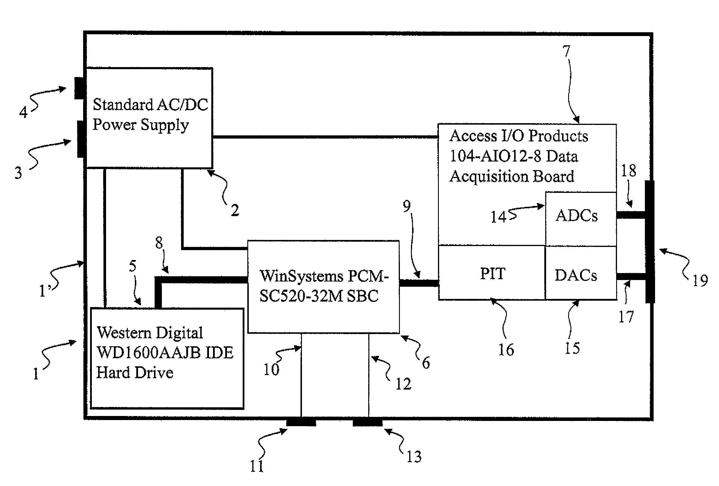
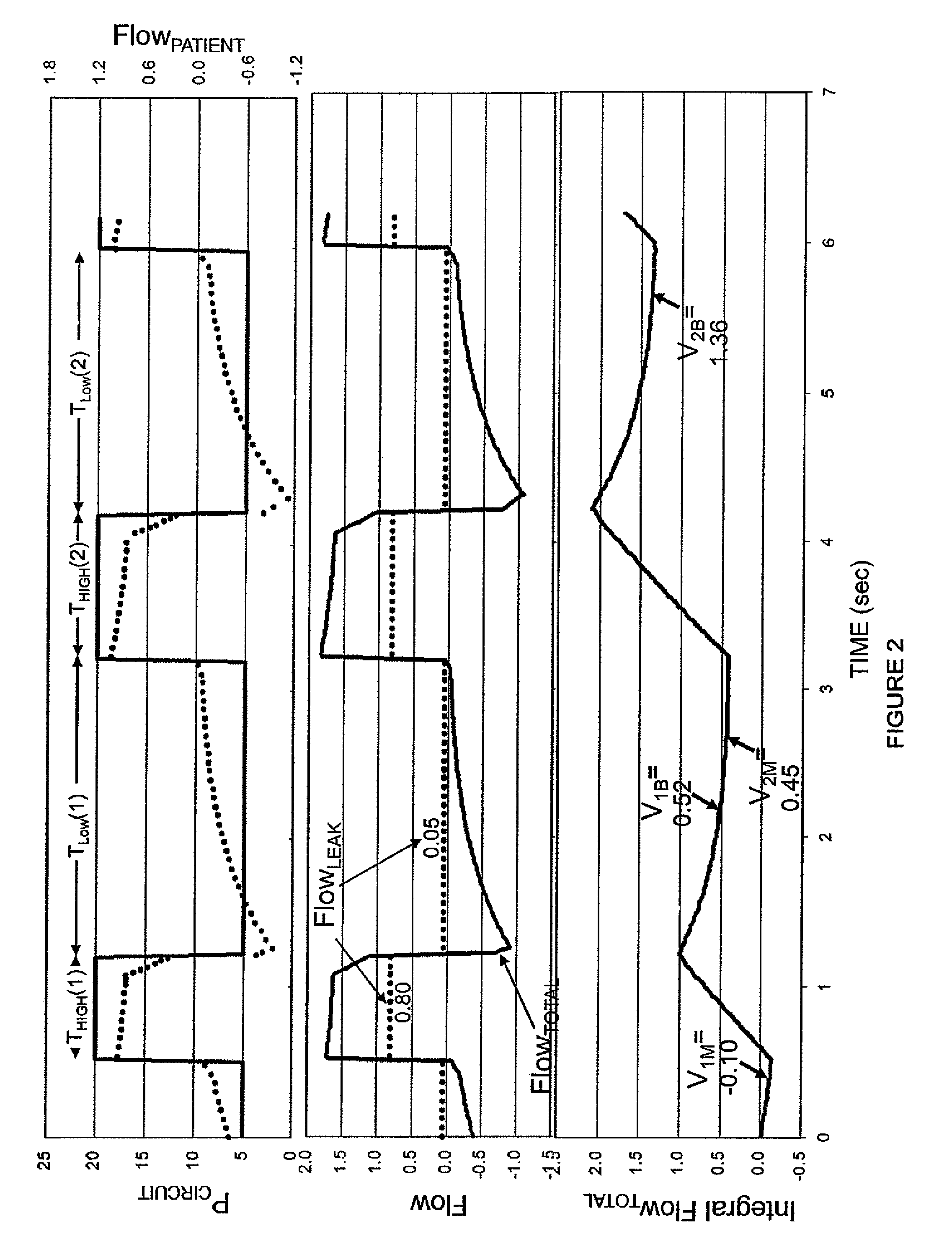
[0120]Two embodiments were built. The first was a non-real time system used to develop, test and refine the algorithms. This embodiment utilized a desktop computer and the algorithms were coded using the Matlab system. It incorporated all the four methods proposed to generate indices that reflect pattern of pressure delivery (Methods 2A to 2D in the Detailed Description of the Invention section). Testing of this embodiment was done using digital files recorded previously, which contained signals corresponding to circuit pressure and flow rate measured during mechanical ventilation of several patients. The original flow rate signals in these files did not incorporate any leaks as they were obtained during invasive ventilation with a tight tracheal seal. A virtual leak was added to the flow rate signal by generating a new channel (Flow+Leak) comprised of the original flow rate signal plus a function related to the recorded circuit pressure, representing a specified...


PUM


Abstract

Gas leakage from a ventilator circuit and patient interface is estimated by a method that relies on breath-by-breath or time-to-time variability in the pattern of pressure delivery by the ventilator, comprising generating signals that correspond to pressure (PCIRCUIT) and flow rate (Flow) in the ventilator circuit, integrating flow (Integrated Flow), measuring the change in Integrated Flow (ΔV) over an INTERVAL extending from a selected point in the expiratory phase of a ventilator cycle to a selected point during the expiratory phase of a nearby ventilator cycle, repeating the measurement of ΔV for at least two said INTERVALs, processing PCIRCUIT to produce an index or indices that reflect(s) the pattern of pressure delivery by the ventilator during each of said INTERVALs, applying statistical methods to determine the relation between the differences in ΔV among 1NTERVALs and the corresponding differences in said index or indices of PCIRCUIT, and establishing from said relation the leak rate at specified PCIRCUIT values.

Description

REFERENCE TO RELATED APPLICATIONS[0001]This application is a U.S. National Phase filing under 35 USC 371 of PCT / CA2010 / 000134 filed Jan. 29, 2010 claiming priority under 35 USC 119(e) from U.S. Provisional Patent Application No. 61 / 202,123 filed Jan. 29, 2009.FIELD OF INVENTION[0002]The invention relates to ventilators.BACKGROUND TO THE INVENTION[0003]Ventilators are typically connected to patients via tubing and an interface. In invasive ventilation, the interface is usually a tube inserted in the patient's trachea (endotracheal tube; ET tube). A seal is usually maintained by inflating a cuff around the stem of the ET tube. In non-invasive ventilation (NIV), the interface is usually a mask or a helmet applied to the face / head around the patient's external airway (nose and / or mouth). A seal is maintained usually by applying appropriate tension to the straps holding the interface in place. In both invasive and non-invasive ventilation, the seal is at times imperfect resulting in air ...

Claims


Application Information

Patent Timeline
Patent Type & Authority Patents(United States)
IPC IPC(8): A61M16/00
CPCA61M2205/50A61M2016/0027A61M16/0051A61M2205/15A61M2016/0021A61M2016/0033A61M2205/52A61M16/021
Inventor YOUNES, MAGDY
Owner YRT
Why Eureka
Try Eureka