Gear driven knife drive mechanism

a drive mechanism and drive mechanism technology, applied in the field of surgical instruments, can solve the problems of not providing at least one-directional articulation of about 90 degrees without sacrifi

Active Publication Date: 2014-12-16
COVIDIEN LP
View PDF12 Cites 797 Cited by
  • Summary
  • Abstract
  • Description
  • Claims
  • Application Information

AI Technical Summary

Problems solved by technology

However, existing surgical instruments do not provide at least one-directional articulation of about 90 degrees without sacrificing the existing important benefits of the surgical instrument.

Method used


Image

  • Gear driven knife drive mechanism
  • Gear driven knife drive mechanism
  • Gear driven knife drive mechanism

Examples


Embodiment Construction

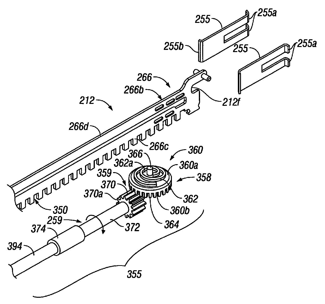
[0047]Embodiments of the presently disclosed endoscopic surgical stapling apparatus will now be described in detail with reference to the drawings, in which like reference numerals designate identical or corresponding elements in each of the several views.

[0048]In the drawings and in the description that follows, the term “proximal”, as is traditional, will refer to the end of the stapling apparatus which is closest to the operator, while the term distal will refer to the end of the apparatus which is furthest from the operator.

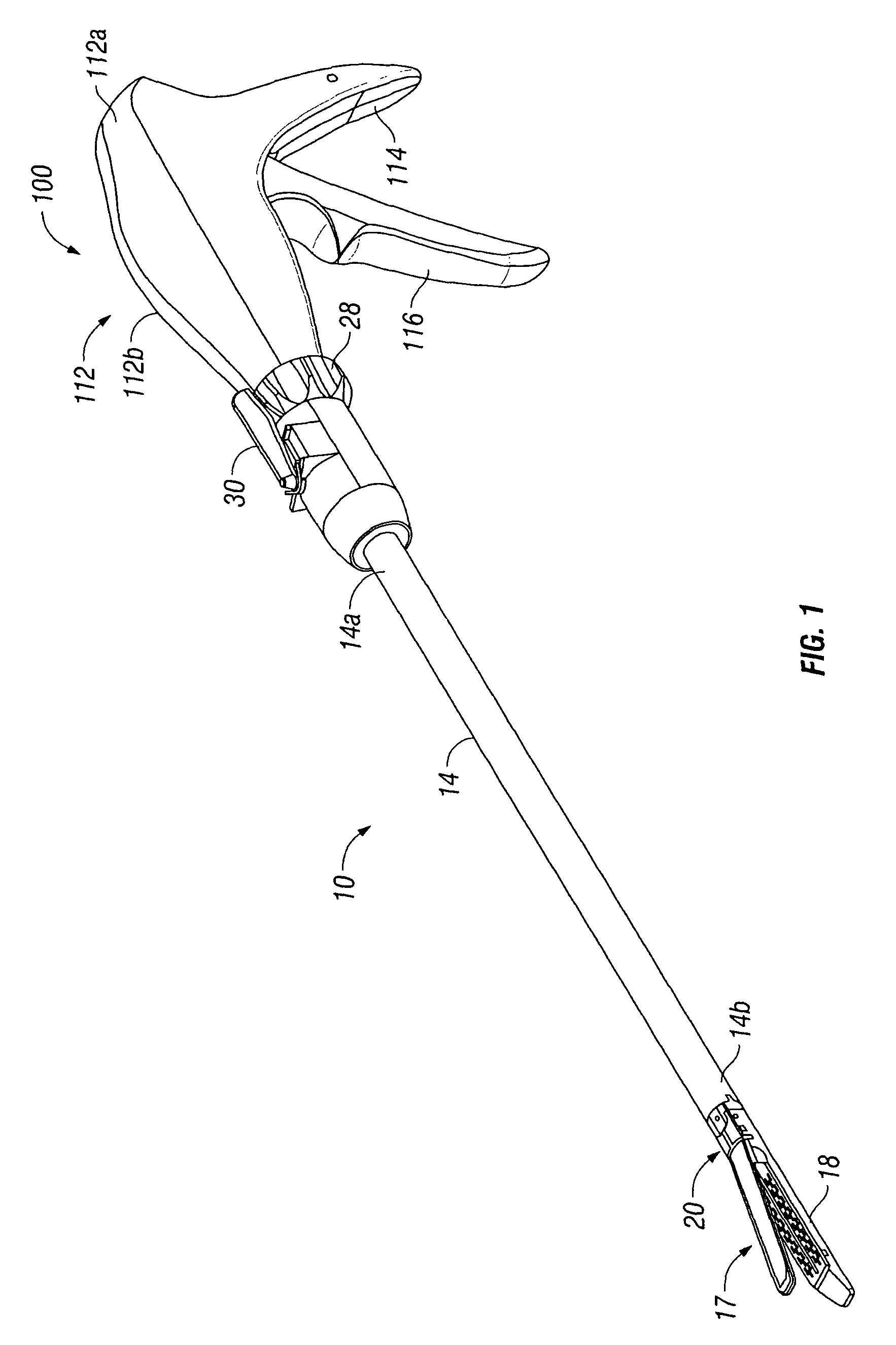
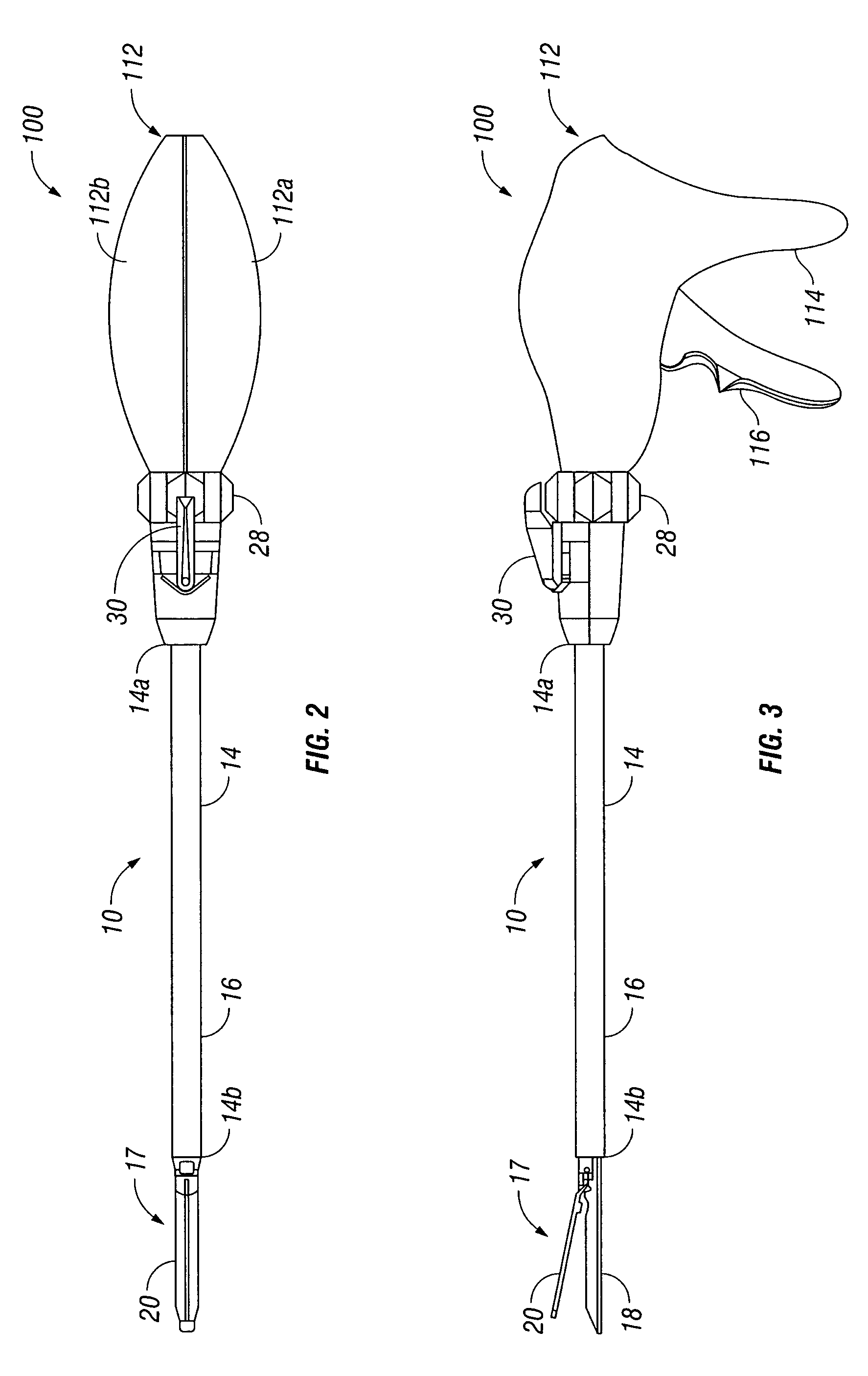
[0049]Referring now to FIGS. 1-4, a surgical stapling apparatus for applying surgical staples is shown generally as surgical stapling apparatus 10. Surgical stapling apparatus 10 generally includes a handle assembly 100. The handle assembly 100 includes proximal housing portion 112, which may be formed as two separate housing halves 112a and 112b and a handle portion 114 extending from housing portion 112. The handle assembly 100 includes a trigger 116 that i...


PUM

PropertyMeasurementUnit
angleaaaaaaaaaa
angleaaaaaaaaaa
lengthaaaaaaaaaa

Abstract

A surgical apparatus includes a handle assembly, an elongated body portion defining a first longitudinal axis, a tool assembly pivotally supported on the distal end of the elongated body portion to form a pivot axis, and a flexible drive assembly that includes a flexible drive member extending from a position proximal of the pivot axis to a position distal of the pivot axis. The drive member has a distal end which is movable in relation to the tool assembly and a gear drive assembly to enable movement of the distal end of the flexible drive member. The flexible drive assembly includes a flexible knife drive beam that advances or retracts via a primary drive gear meshing with the flexible knife drive beam to effect movement of the flexible knife drive beam.

Description

BACKGROUND[0001]1. Technical Field[0002]This application relates to a surgical apparatus, and more particularly, to an articulating mechanism for use with an endoscopic surgical stapling apparatus for applying a plurality of surgical fasteners to body tissue and optionally incising fastened tissue.[0003]2. Background of Related Art[0004]Surgical devices wherein tissue is first grasped or clamped between opposing jaw structure and then joined by surgical fasteners are well known in the art. In some instruments a knife is provided to cut the tissue which has been joined by the fasteners. The fasteners are typically in the form of surgical staples but two part polymeric fasteners can also be utilized.[0005]Instruments for this purpose can include two elongated members which are respectively used to capture or clamp tissue. Typically, one of the members carries a staple cartridge which houses a plurality of staples arranged in at least two lateral rows while the other member has an anvi...

Claims


Application Information

Patent Timeline
Patent Type & Authority Patents(United States)
IPC IPC(8): A61B17/00A61B17/04A61B17/29A61B17/072
CPCA61B2017/00685A61B2017/2934A61B17/07207A61B2017/2937A61B2017/2943A61B2017/2927
Inventor VIOLA, FRANK, J.
Owner COVIDIEN LP
Why Eureka
Try Eureka