Inter-axle differential lock shift mechanism

a technology of inter-axle differential and shift mechanism, which is applied in the direction of mechanical actuated clutches, inter-engaging clutches, and gearing. it can solve the problems of consuming valuable space and material in the axle assembly housing, reducing the production cost of these components, and reducing the cost of tooling and production costs. , reducing space and material requirements, reducing tooling and production costs

Inactive Publication Date: 2007-05-01
DANA HEAVY VEHICLE SYSTEMS GROUP LLC
View PDF54 Cites 60 Cited by
  • Summary
  • Abstract
  • Description
  • Claims
  • Application Information

AI Technical Summary

Benefits of technology

[0012]A clutch in accordance with the present invention is advantageous as compared to existing locking clutches for inter-axle differentials. The inventive clutch aligns the actuator and the clutch member thereby reducing space and material requirements in the axle assembly housing. The inventive clutch also eliminates the need for a pushrod and shift fork thereby reducing tooling and production costs, as well as eliminating the issues associated with misalignment of the piston and pushrod, relative rotation of the shift fork and clutch member, and tipping of the shift fork.

Problems solved by technology

For example, during hazardous driving conditions it may be necessary to prevent power from being delivered to a wheel that has lost traction.
First, the pushrod and piston are commonly located at a radial distance from the clutch members thereby consuming valuable space and material in the axle assembly housing.
Second, tooling for the piston, pushrod and shift fork are relatively expensive, and production of these components is also relatively expensive.
Third, relative rotation occurs between the shift fork and clutch member that causes wear on the shift fork.
Fourth, the tendency to place the piston and pushrod bores in separate parts creates misalignment concerns.
Finally, the offset load applied to the shift fork by the pushrod causes the shift fork to tip, increasing wear on the fork and clutch member and potentially resulting in binding of the clutch splines.

Method used


Image

  • Inter-axle differential lock shift mechanism
  • Inter-axle differential lock shift mechanism
  • Inter-axle differential lock shift mechanism

Examples


Embodiment Construction

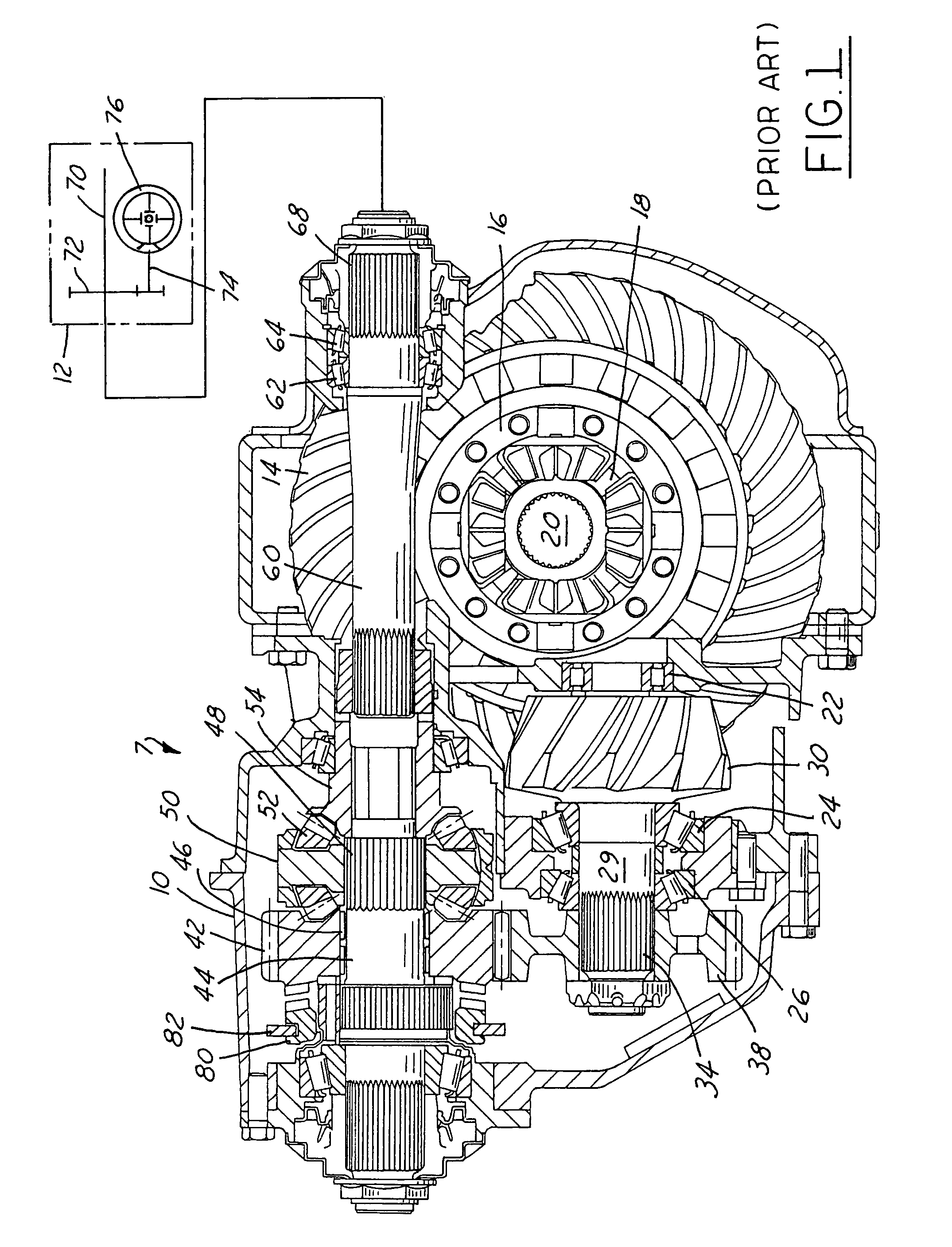
[0032]Referring to FIG. 1 an arrangement 7 of an axle assembly with an interaxle differential for a vehicle having at least first and second drive axles is provided. The casing 10 for the front axle is shown in section and the casing for the rear axle 12 is shown schematically. The arrangement 7 has rotatably mounted therein for the front axle a ring gear 14. The ring gear 14 mounts a carrier 16. The carrier 16 along with side gears 18 (only one shown) forms a front axle differential for the half shafts (only one shown) 20 of the front axle. Rotatably mounted in the casing 10 by a front end bearing 22 and tapered thrust bearings 24, 26 is a counter shaft 29 with a pinion gear 30 along its end. The pinion gear 30 is meshed with the ring gear 14. On a second opposite end 34 of the counter shaft there is mounted by a splined connection driven gear 38. The driven gear 38 is meshed with a side gear 42. The example shown is a helical gear; however, gear 42 can be a spur or other parallel ...


PUM


Abstract

An improved inter-axle differential locking clutch is provided that aligns the actuator and the clutch member thereby reducing space and material requirements in the axle assembly housing. The clutch also eliminates the need for a pushrod and shift fork thereby reducing tooling and production costs, as well as eliminating issues associated with misalignment of the piston and pushrod, relative rotation of the shift fork and clutch member, and tipping of the shift fork. The clutch includes one or more pistons disposed within either the axle housing or a carrier supporting the input shaft bearing. Fluid pressure actuates the pistons against a clutch member causing selective engagement between the clutch member and either a side gear driven by the inter-axle differential or a differential case housing the differential gears of the inter-axle differential.

Description

[0001]This application claims priority to and is a continuation-in-part of U.S. patent application Ser. No. 10 / 288,686 filed Nov. 6, 2002, now U.S. Pat. No. 6,918,851, the entire disclosure of which is incorporate herein by reference.BACKGROUND OF THE INVENTION[0002]1. Field of the Invention[0003]The present invention relates to an inter-axle differential, and more particularly, to an improved locking clutch for inter-axle differentials.[0004]2. Discussion of Related Art[0005]A conventional tandem axle assembly for heavy-duty trucks used in on-road and off-road service includes forward and rear axle assemblies and an intermediate drive shaft assembly connecting the two axle assemblies. The forward and rear axle assemblies each include a pair of axle half shafts extending therefrom on which one or more wheels of a vehicle are mounted. The axle half shafts in each axle assembly are driven by a wheel differential. The wheel differential includes a pinion gear in mesh with a ring gear (...

Claims


Application Information

Patent Timeline
Patent Type & Authority Patents(United States)
IPC IPC(8): F16H48/20B60K17/16B60K17/346B60K17/36F16D11/10F16D25/08F16H48/06F16H48/08F16H48/24F16H48/30F16H48/32
CPCB60K17/16B60K17/3462B60K17/36F16D11/10F16D25/082F16H57/04F16H48/08F16H48/24F16H48/30F16H48/32F16H2048/02F16H2200/2071
Inventor GREEN, MICHAELPOLLACK, CHRISTURNER, GARY A.WENSTRUP, LEOZIECH, JAMES F.
Owner DANA HEAVY VEHICLE SYSTEMS GROUP LLC
Why Eureka
Try Eureka