Image forming apparatus

a technology of forming apparatus and forming plate, which is applied in the direction of printing, other printing apparatus, etc., can solve the problems of deteriorating discharged paper alignment, remarkably occurring problems, and failure of paper discharge, so as to achieve precise operation of orderly alignment and loading, reduce paper thickness, and weak rigidity

Active Publication Date: 2014-12-23
RISO KAGAKU CORP
View PDF8 Cites 0 Cited by
  • Summary
  • Abstract
  • Description
  • Claims
  • Application Information

AI Technical Summary

Benefits of technology

[0011]With the image forming apparatus according to claim 1, the conveying means is controlled in accordance with at least one of the discharge angle and the kind of the paper to be used upon the paper discharge to the paper discharge tray to thereby adjust the discharge speed upon the paper discharge to the paper discharge tray. Thus, with even thin paper with weak rigidity or even in a case where resistance received from air by the discharged paper is increased by the discharge angle, the paper is discharged onto the paper discharge tray at the appropriately controlled discharge speed; therefore, for example, paper deformation such as rising of a tip end part hardly occurs, and thus paper discharge failure, deteriorated discharged paper alignment, etc. attributable to this hardly occur.
[0012]With the image forming apparatus according to claim 2, the discharge speed of the first sheet of the paper is faster than that of the second and subsequent sheets of the paper with an increase in the discharge angle measured with the paper oriented upwardly from the horizontal direction and with a decrease in the paper thickness, which therefore permits orderly alignment and loading onto the paper discharge tray starting with the first sheet of a print in particular.
[0013]With the image forming apparatus according to claim 3, specifying the kind of the paper to be used by the paper specifying means and specifying the paper discharge tray by the paper discharge tray specifying means permit the control means to read, from the storage means, the appropriate paper discharge speed corresponding to the above specification and discharge the first sheet of the paper at this discharge speed and also discharge the second and subsequent sheets of the paper at a slower speed. Therefore, for various combinations of a plurality of paper kinds and a plurality of paper discharge trays, a precise operation of performing orderly alignment and loading starting with the first sheet of the print can easily be performed by anyone without relying on experience.
[0014]With the image forming apparatus according to claim 4, in addition to the aforementioned control of the paper discharge speed above in correspondence with at least one of the paper discharge angle and the paper kind, with a further increase in the discharge angle and with a decrease in the paper thickness, the space between the stiffening members when contacted by the first sheet of the paper is narrowed more than the space when contacted by the second and subsequent sheets of the paper. Thus, in the discharge of especially the first sheet of the paper more susceptible to the air resistance, for example, the deformation such as the rising of the tip end part even more hardly occurs, which can suppress even more reliably the paper discharge failure, the deteriorated discharged paper alignment, etc. attributable to this.

Problems solved by technology

Because of such deformation, the paper may lose its speed and drop so as to cover a discharge port, thereby causing problems specific to the thin paper, including paper discharge failure such as jam and deteriorated discharged paper alignment.
Such problems occur remarkably on the first sheet of a print in particular.

Method used


Image

  • Image forming apparatus
  • Image forming apparatus
  • Image forming apparatus

Examples


Embodiment Construction

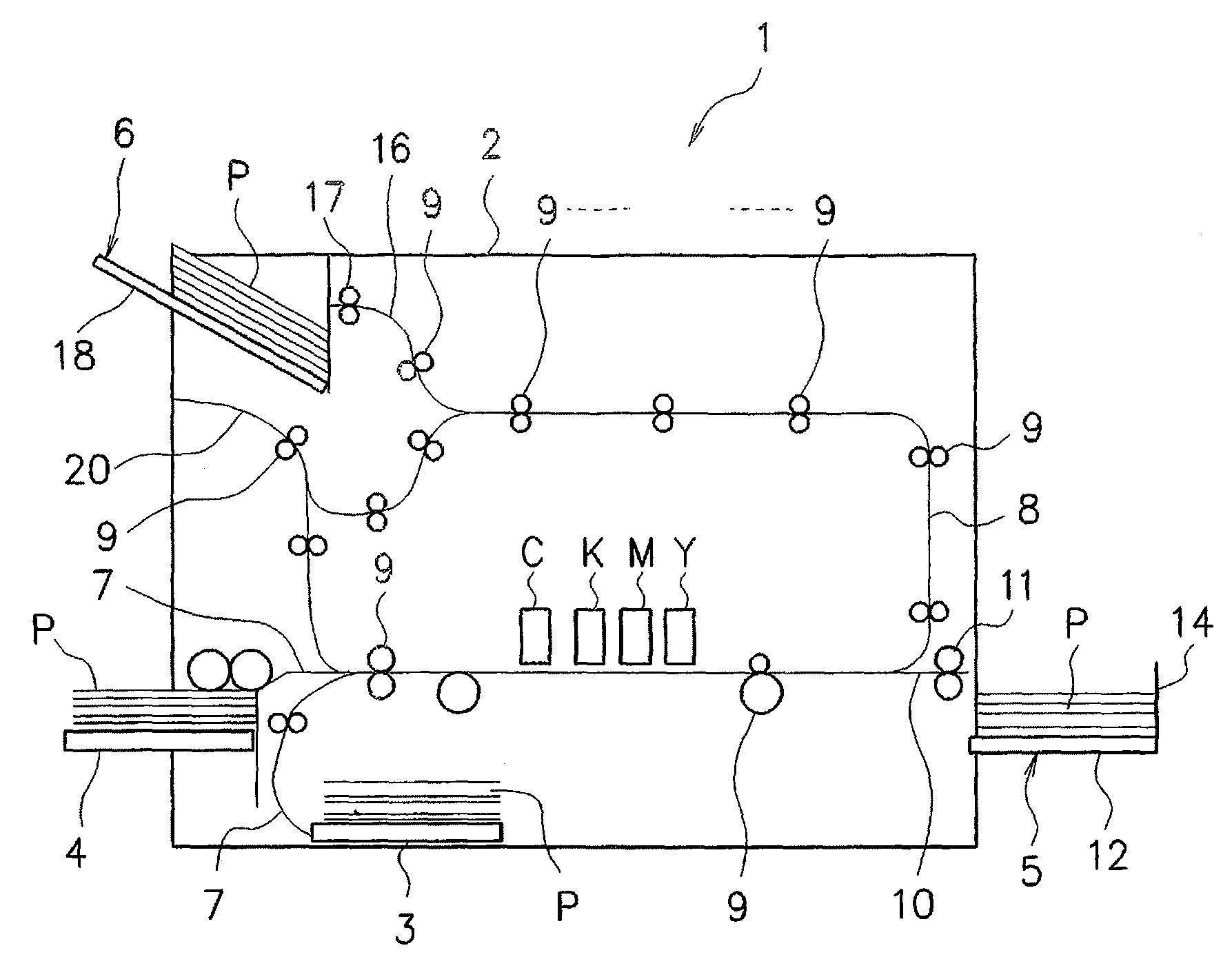
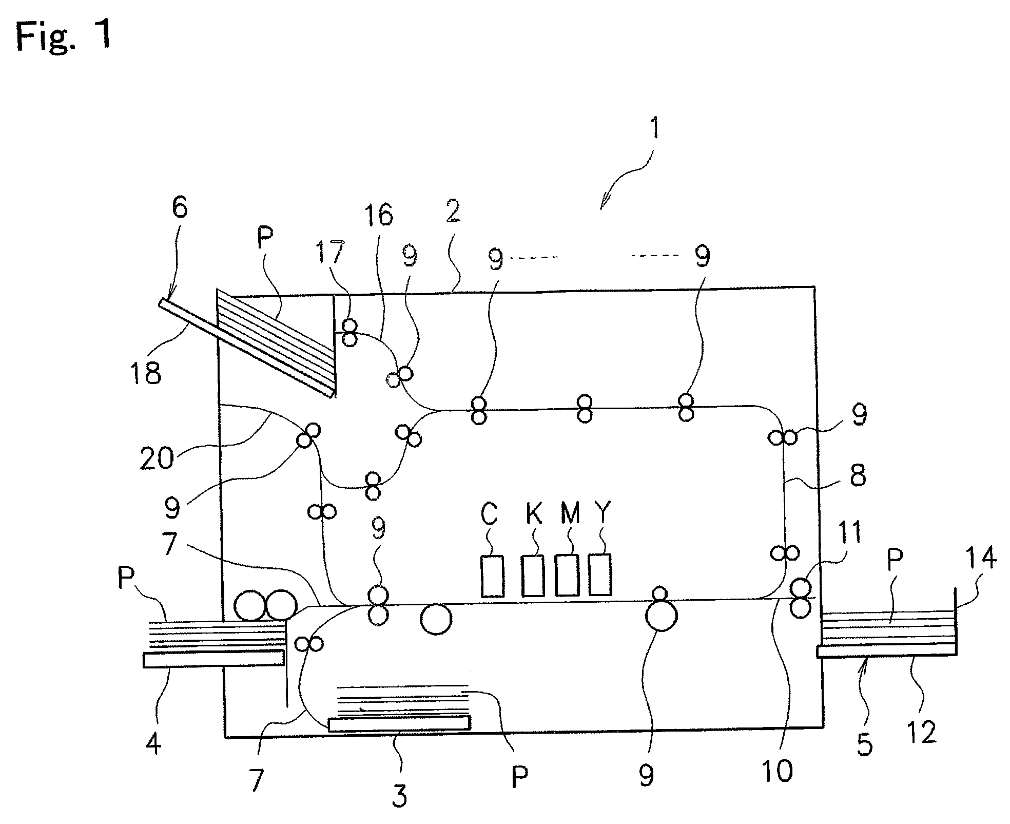
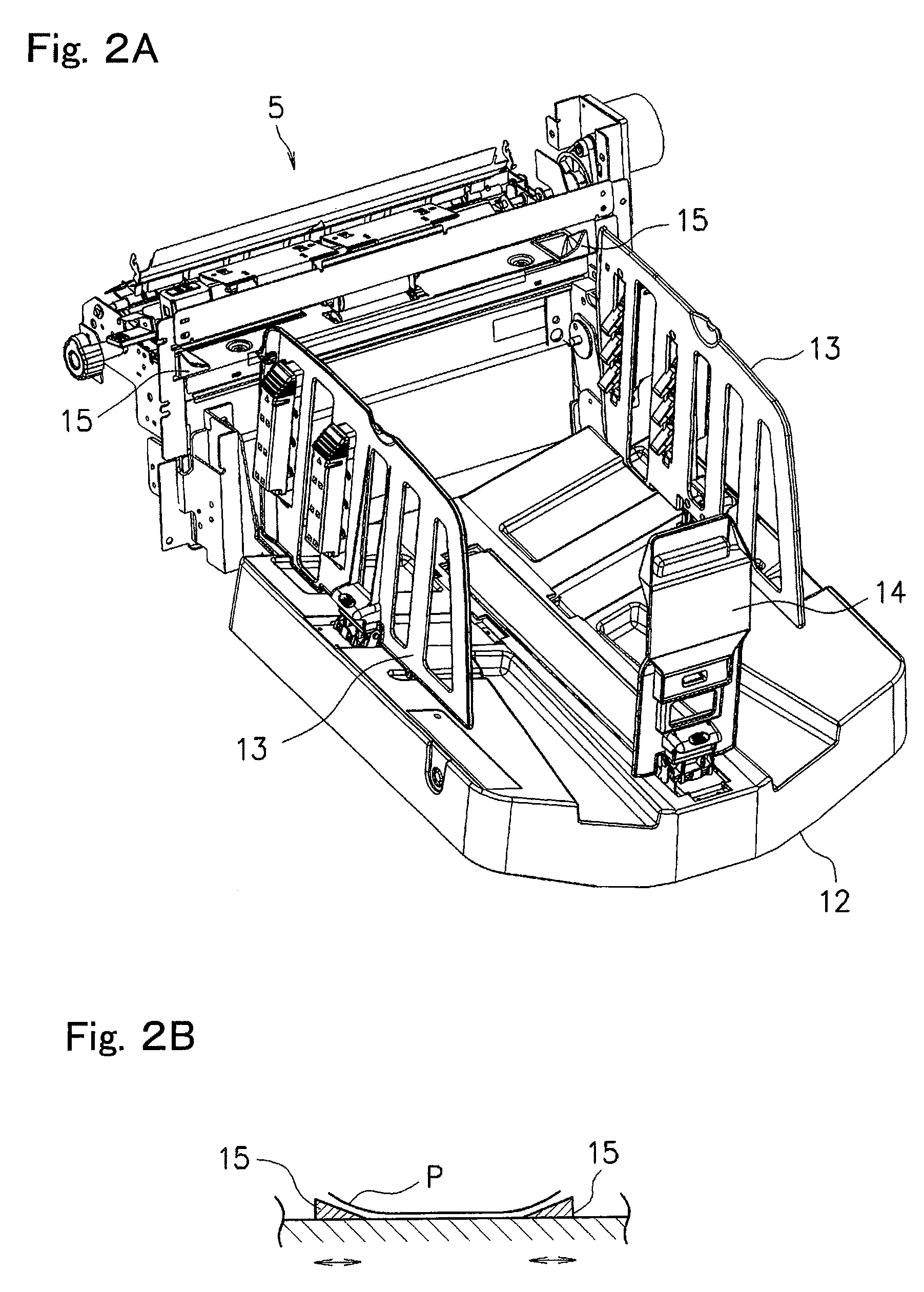
[0023]An image forming apparatus 1 according to an embodiment of the present invention will be described with reference to FIGS. 1 to 6. This image forming apparatus 1 is an apparatus that forms an image on paper and discharges the paper, and is characterized by, especially when thin paper with weak rigidity is used, controlling paper discharge speed, etc. in accordance with a discharge angle and a kind of the paper in order to eliminate risks of deteriorated discharged paper alignment, paper discharge failure, etc. as a result of occurrence of deformation of a tip end at a first discharged page of the paper in particular.

[0024]For the first discharged paper, the thin paper on which the deteriorated discharged paper alignment, the paper discharge failure, etc. possibly occur is, for example, paper having a basis weight of 52 g / m2 or less and, for example, paper having a pure bending rigidity of 75 μN·m2 / m.

[0025]First, a basic structure, etc. of the image forming apparatus 1 will be ...


PUM


Abstract

An image forming apparatus includes a conveying device for conveying paper, an image forming unit for forming an image on the paper, and a paper discharge tray where the image-formed paper is discharged and loaded at a predetermined discharge angle by the conveying device. The conveying device is controlled in a manner that a discharge speed of a first sheet of the paper is different from a discharge speed of second and subsequent sheets of the paper.

Description

RELATED APPLICATIONS[0001]The present application is based on, and claims priority from, Japanese Application No. JP2011-072674 filed Mar. 29, 2011, the disclosure of which is hereby incorporated by reference herein in its entirety.TECHNICAL FIELD[0002]The present invention relates to an image forming apparatus that discharges and loads image-formed paper onto a paper discharge tray, and more specifically to an image forming apparatus capable of orderly aligning and loading even thin paper with weak rigidity in particular onto the paper discharge tray without causing deteriorated discharged paper alignment, paper discharge failure, etc.BACKGROUND ART[0003]In a paper discharge mechanism of an image forming apparatus, especially when print paper such as thin paper with weak rigidity is discharged at time of high-speed printing, deformation such as rising of a tip end part of the paper across its full width or upward and rounded turning of both corner parts of the tip end of the paper ...

Claims


Application Information

Patent Timeline
Patent Type & Authority Patents(United States)
IPC IPC(8): B41J11/00B41J13/00B41J29/38
CPCB41J11/009B41J13/0036
Inventor MORITA, YOSHIHISASHIMODA, TOMOHIKOARAI, HITOSHI
Owner RISO KAGAKU CORP
Why Eureka
Try Eureka