Quick change conveyor roll sleeve assembly and method

a conveyor and roll technology, applied in the direction of charging, lighting and heating apparatus, furniture, etc., can solve the problems of reducing productivity, corroding and degrading the surface of such rolls, and reducing the efficiency of conveyors, so as to prolong the downtime

Inactive Publication Date: 2014-12-23
PYROTECK INC
View PDF9 Cites 79 Cited by
  • Summary
  • Abstract
  • Description
  • Claims
  • Application Information

AI Technical Summary

Problems solved by technology

In such environments, the surface of such rolls are corroded and degraded by the harsh conditions in which they operate.
Thus, the surfaces of such rolls need to undergo maintenance or be replaced on a regular basis, which can lead to down time and reduced productivity.
Likewise, sink rolls and stabilizer rolls used in molten zinc and zinc / aluminum galvanizing baths must be replaced or serviced often due to dross buildup, oxidation and corrosion of the roll surface.

Method used


Image

  • Quick change conveyor roll sleeve assembly and method
  • Quick change conveyor roll sleeve assembly and method
  • Quick change conveyor roll sleeve assembly and method

Examples


Embodiment Construction

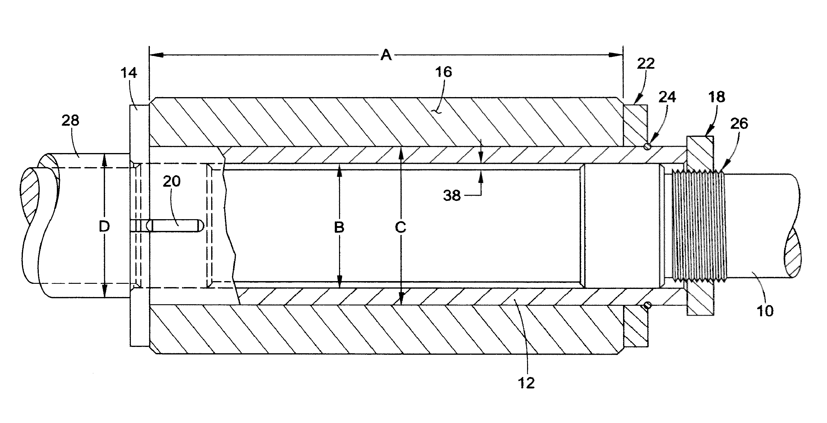
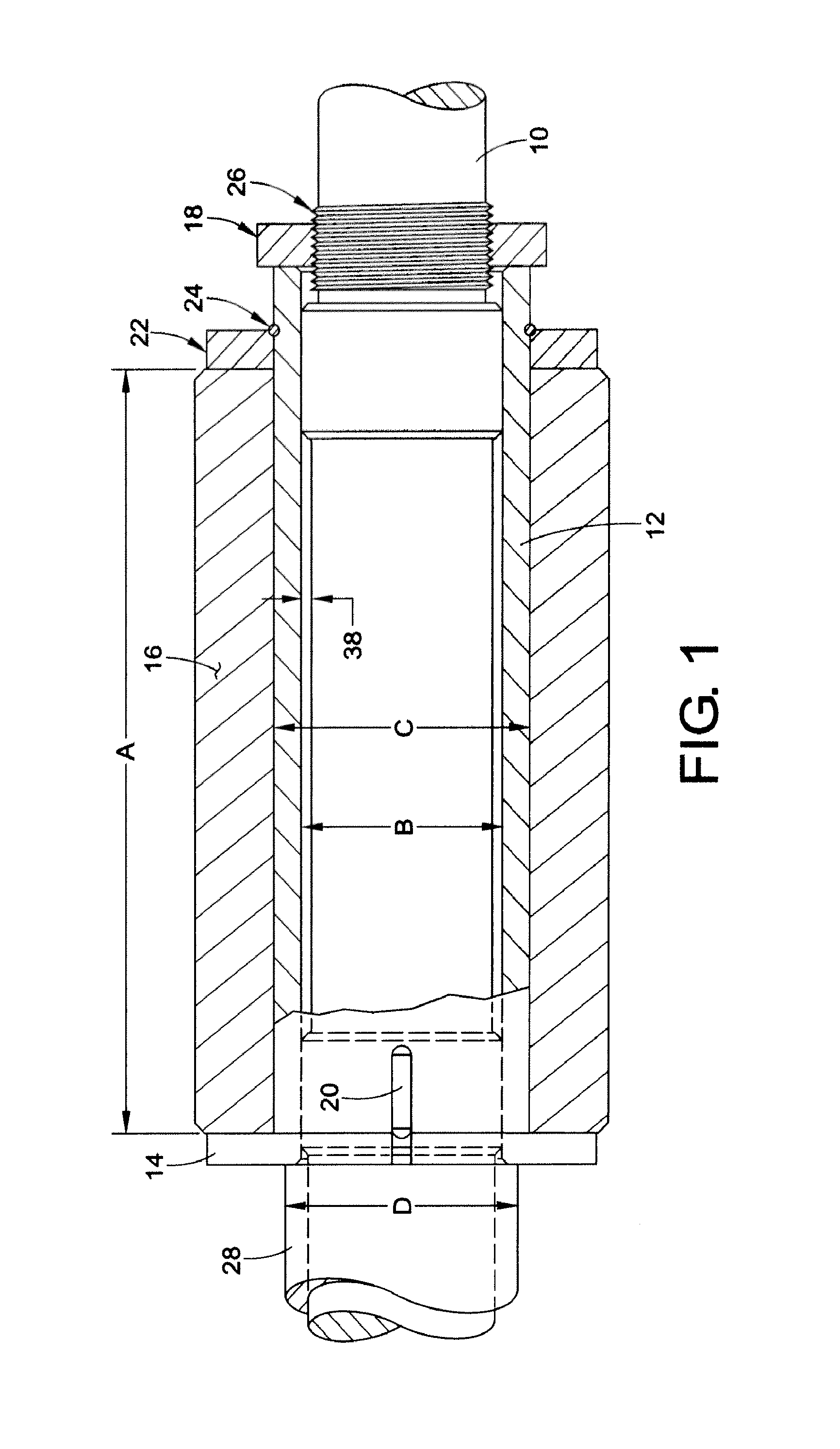
[0033]The present embodiments are directed to the use of removable tubes or sleeves on rolls used in harsh environments that can be slipped over a roll body or inner shaft. Depending on the application, these sleeves can be made from a variety of materials as suited. These sleeves assist in ease of roller maintenance, as fresh sleeves can be readily slipped onto the roll body during equipment down time after removal of the spent insulated roll sleeve instead of servicing the entire roll assembly.

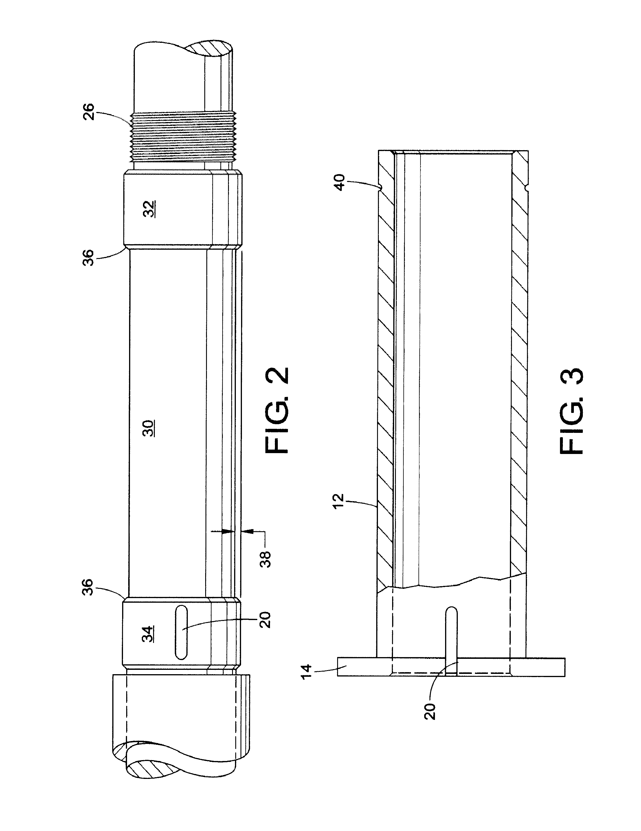
[0034]Therefore, with reference to FIG. 1, in one embodiment, there is provided a roll assembly including a roll shaft or body 10, a removable spool 12 including a collar 14 slidably mounted over the roll shaft, and a roll sleeve 16 mounted on the spool 12. A locking nut 18 threaded onto threads 26 on the roll shaft 10 or other securing component may be used to hold the spool 12 and roll sleeve 16 covering the spool in place on the roll shaft 10. The roll shaft 10 may have a larger diameter ...


PUM

PropertyMeasurementUnit
diameteraaaaaaaaaa
lengthaaaaaaaaaa
lengthaaaaaaaaaa

Abstract

A quick change conveyor roll assembly for metal or glass processing comprising an inner roll shaft having a rigid and elongated cylindrical surface supported and rotationally driven by an associate rotor mean. At least one removable spool having a cylindrical body with a first diameter, a hollow interior therethrough and a collar rigidly adapted at a first end, the collar having a second diameter whereby the second diameter is greater than the first diameter. At least one removable and replaceable insulated roll sleeve being slidably mounted over at least a portion of said removable spool and abutting said collar, the insulated roll sleeve including at least one layer of an insulation material and a securing means operably adjustable to hold said roll sleeve about said removable spool at a second end in a predetermined location on said inner roll shaft.

Description

[0001]This application claims priority to U.S. Provisional Application No. 61 / 210,911, filed Mar. 24, 2009.BACKGROUND[0002]The present invention relates to a device and method of providing a quick change roll sleeve. It finds particular application in conjunction with conveyors in various high temperature applications such as galvanizing baths as well as steel and glass processing applications, and will be described with particular reference thereto. However, it is to be appreciated that the present exemplary embodiment is also amenable to other like applications.[0003]Rolls are used as conveyors in various high temperature applications, such as galvanizing baths as well as steel and glass processing. In such environments, the surface of such rolls are corroded and degraded by the harsh conditions in which they operate. Thus, the surfaces of such rolls need to undergo maintenance or be replaced on a regular basis, which can lead to down time and reduced productivity.[0004]Rolls such...

Claims


Application Information

Patent Timeline
Patent Type & Authority Patents(United States)
IPC IPC(8): C03B35/18F27D3/02B25F5/02C23C2/00C25D7/06C25D17/00B65G39/07
CPCC03B35/181C03B35/183B65G39/07C23C2/003C25D17/00F27D3/026C25D7/0664C03B35/186B65G39/02C03B35/16Y10T29/49549Y10T29/49554Y10T29/4973Y10T29/49545C23C2/00344
Inventor MARCH, TIMOTHY D.POKRZYK, JR., JOHN A.HASCO, DARYLL A.BRIGHT, MARK
Owner PYROTECK INC
Why Eureka
Try Eureka