Tethering system and method for remote device

a remote control and tethering technology, applied in the field of remote control devices, can solve the problems of insurance agents or representatives running a risk of injury, time-consuming claim investigations, and slippery roofs

Active Publication Date: 2015-01-13
STATE FARM MUTAL AUTOMOBILE INSURANCE COMPANY
View PDF18 Cites 47 Cited by
  • Summary
  • Abstract
  • Description
  • Claims
  • Application Information

AI Technical Summary

Benefits of technology

[0020]Still further, the first end of the tether line may include a swivel leader clip mechanism that allows easy clip-on or clip-off to the remote-controlled device.
[0025]In another example of the present disclosure, a method of tethering a remote-controlled device to a target area comprises positioning a tripod on a surface and away from obstacles blocking a view of the target area, attaching a first end of a tether line to a ground support, attaching the second end of the tether line to the remote-controlled device and forming an anchor-point via an eyelet of the tripod. This enables the tether line to flex or bend and the remote-controlled device to maneuver one or more of over or around the target area without interfering with any nearby objects.
[0026]In yet another example of the present disclosure, a method of tethering a remote-controlled device comprises attaching a first end of a tether line to a ground support and removeably attaching a weighted disc having an eyelet to the remote-controlled device. The method further comprises inserting the second end of the tether line through the eyelet of the weighted disc, attaching a second end of the tether line to the remote-controlled device, and carrying the weighted disc to a portion of the roof via the remote-controlled device. The method further comprises releasing the weighted disc to the portion of the roof to anchor the tether line and moving the remote-controlled device over to a target area, forming an anchor-point via the eyelet of the weighted disc. This enables the tether line to flex or bend and the remote-controlled device to maneuver one or more of over or around the target area without interfering with any nearby objects.

Problems solved by technology

Often, the claim investigations can be time-consuming, difficult and even dangerous for the insurance agents or representatives.
When climbing on the roof and attempting to maneuver around the roof for the inspection, the insurance representative runs a risk of injury, especially in difficult weather conditions, where the roof may be slippery because of rain, snow, and / or ice and winds may be severe.
Even if the insurance representative inspects without getting injured, performing the investigation may still be time-consuming.
For example, in situations where the insurance company has received a large number of claims in a short time period, e.g., when a town is affected by a hurricane, tornado, or other natural disaster, the representative may not have time to perform timely claim investigations of all the received claims.
If claim investigations are not performed quickly, property owners may not receive recovery for their losses for long periods of time.
Additionally, long time delays when performing claim investigations can lead to inaccurate investigation results, e.g., the delay may lead to increased opportunity for fraud and / or may make it more difficult to ascertain the extent of damage at the time of the accident or loss.
However, current Federal Aviation Administration (FAA) regulations may limit and / or prevent the use of such devices in the air for commercial purposes.
More specifically, while remote devices have limited range and altitude, there is a small potential for interference with national airspace and potential mid-air collisions during operation, especially if the remote devices are operating around or near an airport.
Controlling such tethered devices, however, presents its own set of problems.
For example, tree limbs, electrical wires, and other obstacles are often between the target area where the device is needed, such as a roof, and the origin of a tether line.
This is a particular challenge when the tethered device is operating on or above a house or other building where the line can get caught in tree limbs and electrical wires.
Untethered devices have a different challenge.
While untethered devices can avoid tree limbs and other obstacles that may interfere with a tether line, without a physical tether line, untethered devices run the risk of straying onto a neighbor's property or worse, such as into some irretrievable location like a river or wooded area.

Method used


Image

  • Tethering system and method for remote device
  • Tethering system and method for remote device
  • Tethering system and method for remote device

Examples


Embodiment Construction

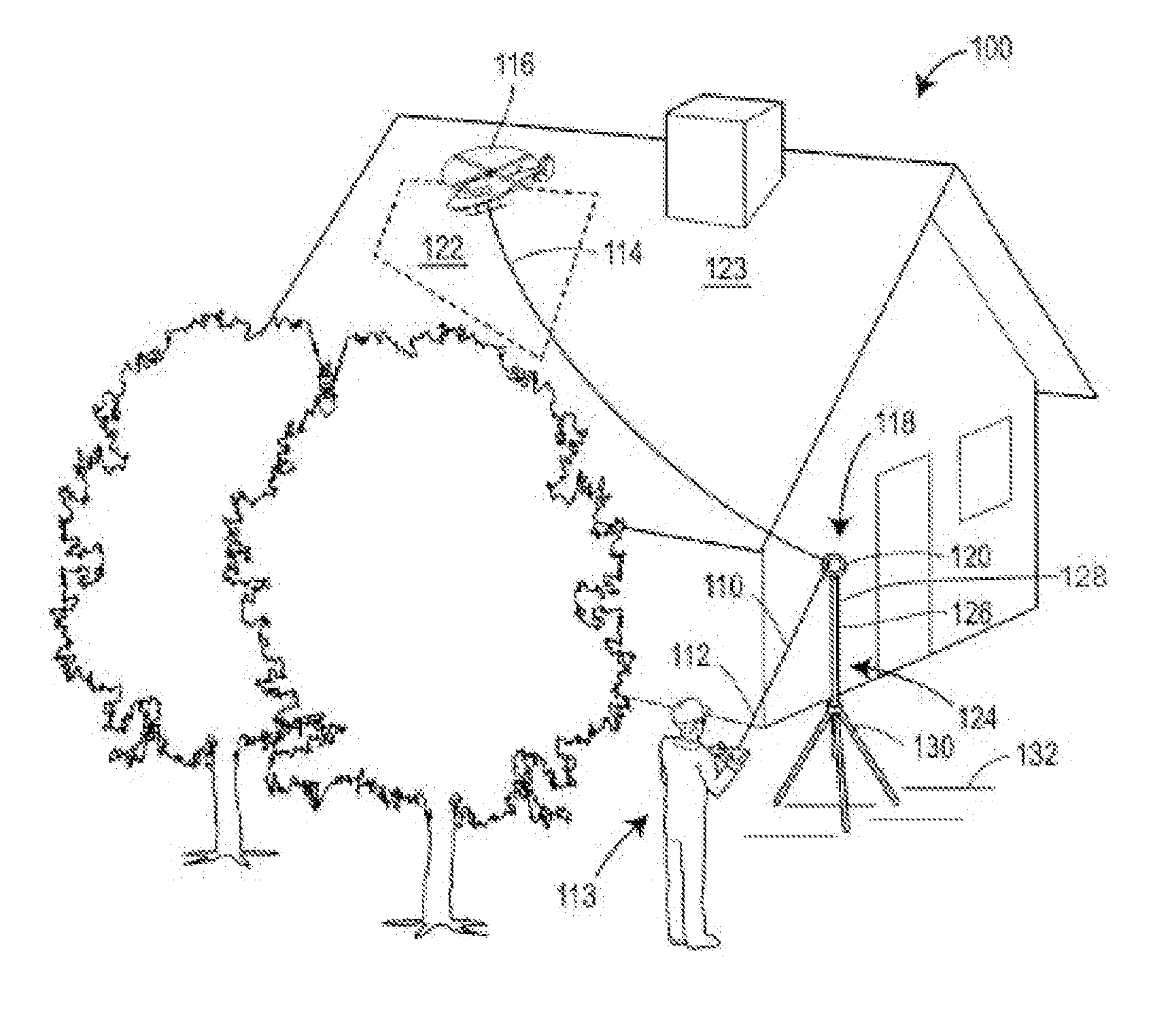
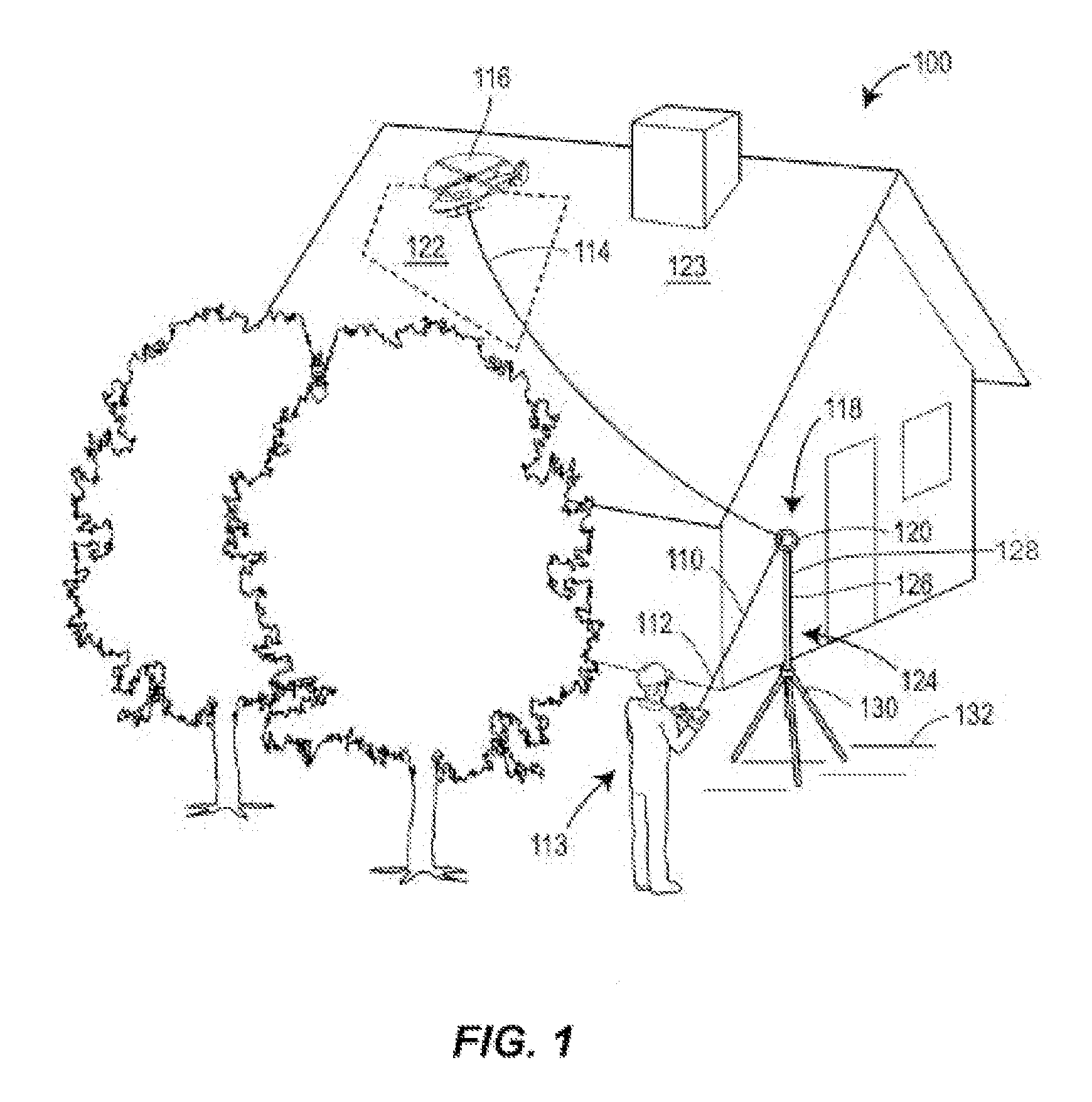
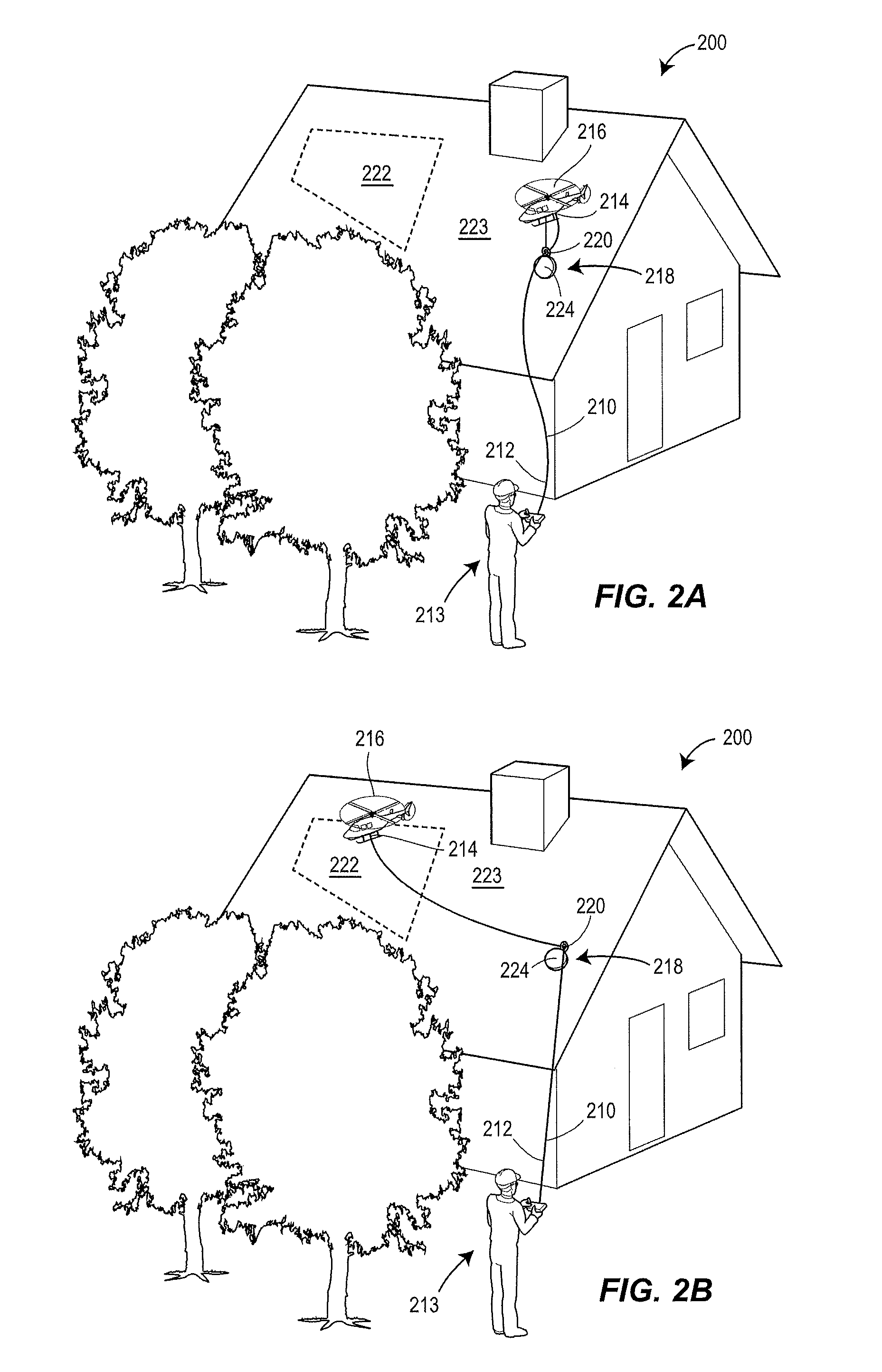
[0028]Generally, a tethering system and method for a remote-controlled device is disclosed. The tethering system includes a tether line having a first end adapted to be connected to a ground support and a second end adapted to be secured to the remote-controlled device. An anchor-point is disposed between the first and second ends of the tether line and includes an eyelet for securing the tether line and allowing the tether line to slide through the eyelet during use. The anchor-point may include a telescoping, extendible tripod or a weighted disc, as explained in more detail below. Both anchor-points, e.g., the tripod and the weighted disc, enable the tether line to bend or flex and the remote-controlled device to maneuver over or on a target area without interfering with any nearby objects.

[0029]Referring now to FIG. 1, an example tethering system 100 of the present disclosure is illustrated. The tethering system 100 includes a tether line 110 having a first end 112 or start point...


PUM

PropertyMeasurementUnit
heightaaaaaaaaaa
radiusaaaaaaaaaa
areaaaaaaaaaaa

Abstract

A tethering system for a remote-controlled device includes a tether line having a first end adapted to be connected to a ground support and a second end adapted to be connected to the remote-controlled device. The system further includes an anchor-point disposed between the first and second ends of the tether line, the anchor point having an eyelet for securing the tether line and allowing the tether line to slide through the eyelet during use. The anchor-point and eyelet enable the tether line to flex or bend and the remote-controlled device to maneuver one or more of over or around the target area without interfering with any nearby obstructions.

Description

FIELD OF THE DISCLOSURE[0001]This disclosure relates to remote-controlled devices, and in particular, to a tethering system and method for remote-controlled devices.BACKGROUND OF THE DISCLOSURE[0002]After an accident or loss, property owners typically file claims with their insurance companies. In response to these claims, insurance agents or representatives investigate the claims to determine the extent of damage and / or loss, ultimately providing their clients with appropriate compensation.[0003]Often, the claim investigations can be time-consuming, difficult and even dangerous for the insurance agents or representatives. For example, to investigate a claim for damage to a homeowner's roof, an insurance representative may have to climb onto the roof and perform inspections while on the roof. When climbing on the roof and attempting to maneuver around the roof for the inspection, the insurance representative runs a risk of injury, especially in difficult weather conditions, where th...

Claims


Application Information

Patent Timeline
Patent Type & Authority Patents(United States)
IPC IPC(8): F16G11/12
CPCA63H30/02A63H27/04B64C39/022B64C39/024F16G11/12B64C2201/145B64C2201/148Y10T24/10Y10T29/49826Y10T24/31B64U2201/104B64U2201/202G05D1/0866G05D1/0033B64U70/97B64U10/60
Inventor FREEMAN, JAMES M.SCHMIDGALL, ROGER D.HARVEY, BRIAN N.TOFTE, NATHAN LEE
Owner STATE FARM MUTAL AUTOMOBILE INSURANCE COMPANY
Why Eureka
Try Eureka