LED lamp with vertical airflow channel

a technology of airflow channel and led lamp, which is applied in the direction of semiconductor devices for light sources, fixed installations, lighting and heating apparatus, etc., can solve the problems of poor heat dissipation effect of led lamps, the airflow channel defined between the cooling fins cannot extend only along horizontal directions, and the wavelength of light emitted by led lamps will have redshi

Inactive Publication Date: 2015-01-13
FOXSEMICON INTEGRATED TECH INC
View PDF3 Cites 24 Cited by
  • Summary
  • Abstract
  • Description
  • Claims
  • Application Information

AI Technical Summary

Problems solved by technology

However, wavelength of the light emitted by the LED lamps will have redshift if the heat generated by the LED lamp lighting device accumulates.
However, due to block of the lamp shells of the lamps, airflow channels defined between the cooling fins can only extend along horizontal directions.
That is to say, the airflow can only flow through the channels along the horizontal direction, resulting in poor heat dissipation effect of the lamps.

Method used


Image

  • LED lamp with vertical airflow channel
  • LED lamp with vertical airflow channel
  • LED lamp with vertical airflow channel

Examples


Embodiment Construction

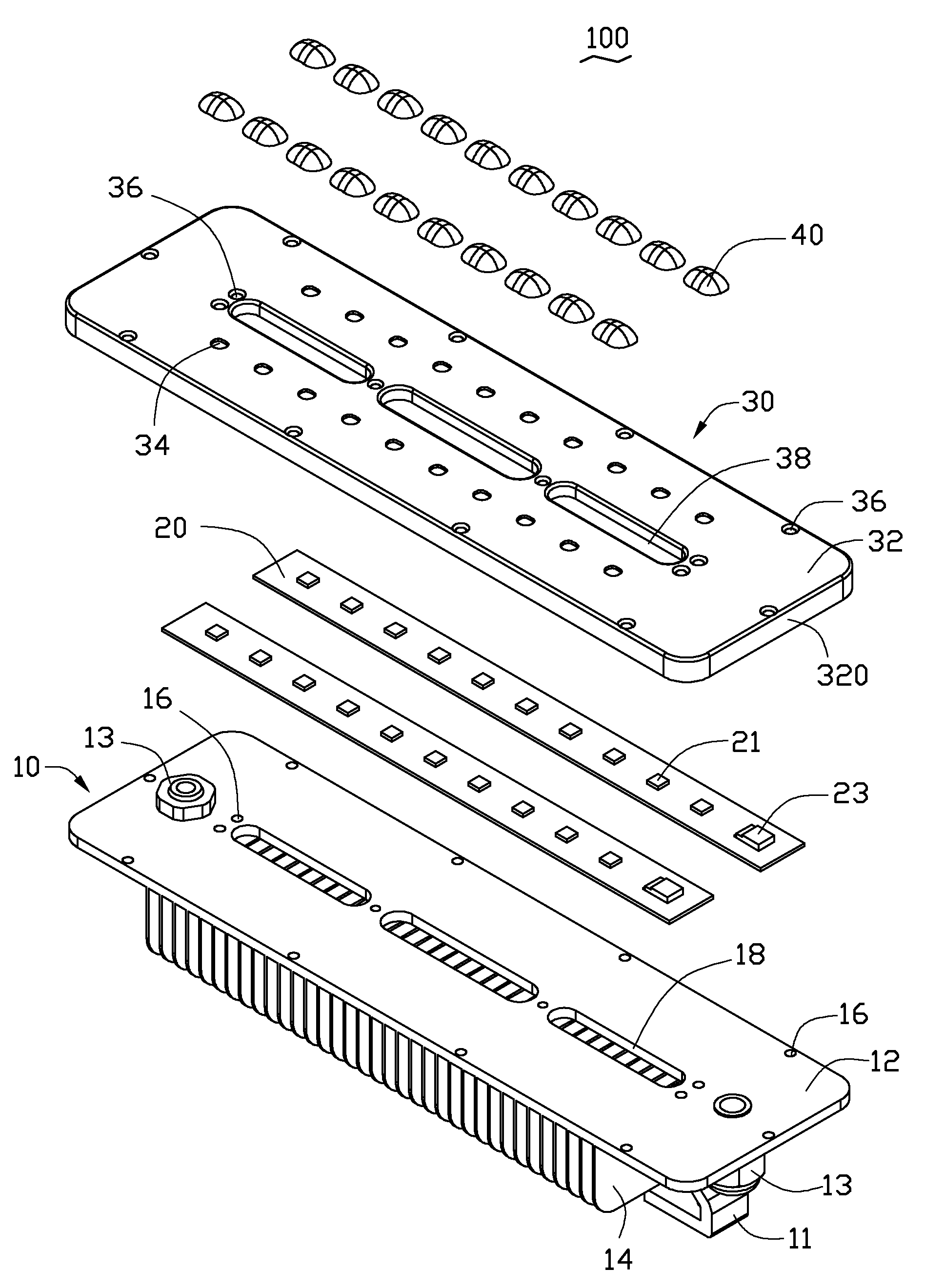
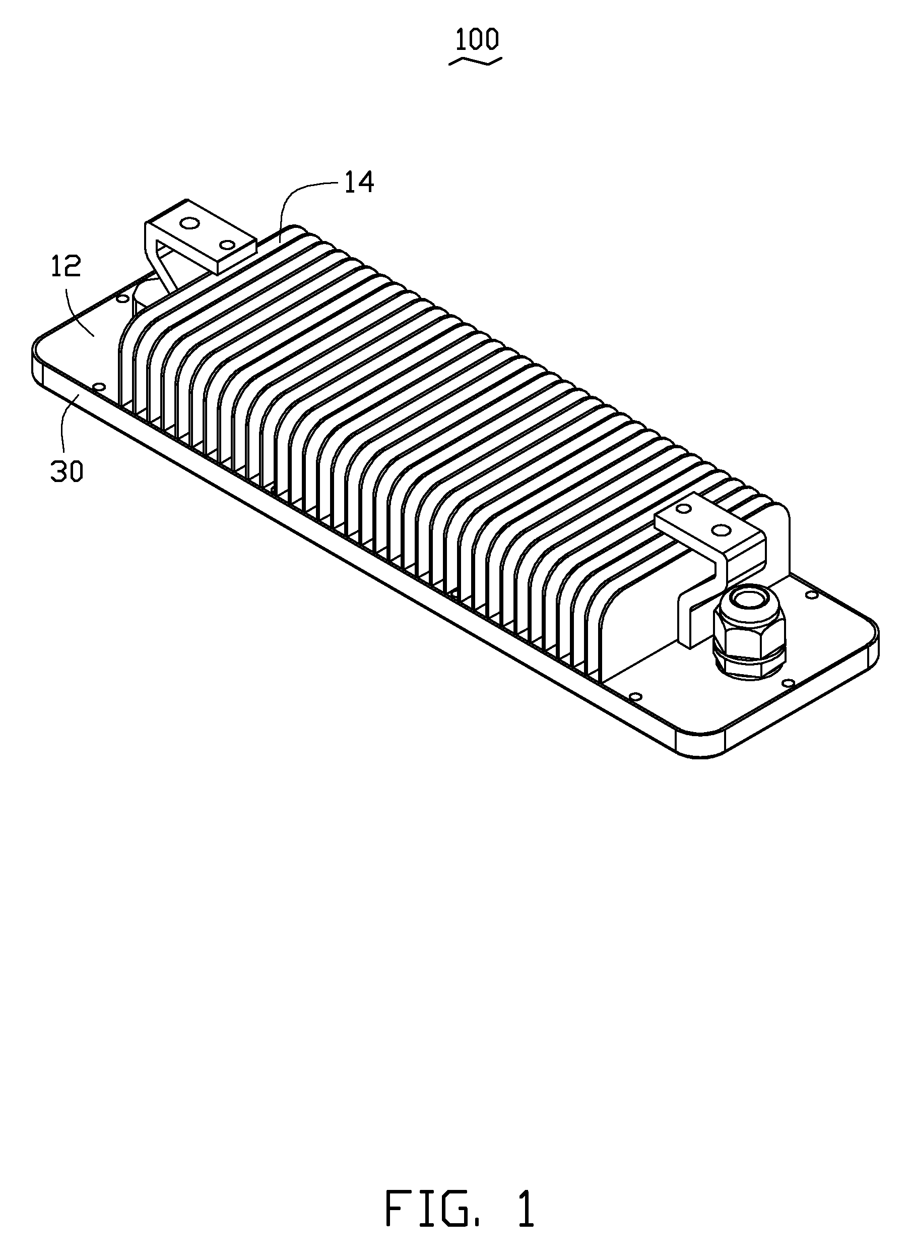
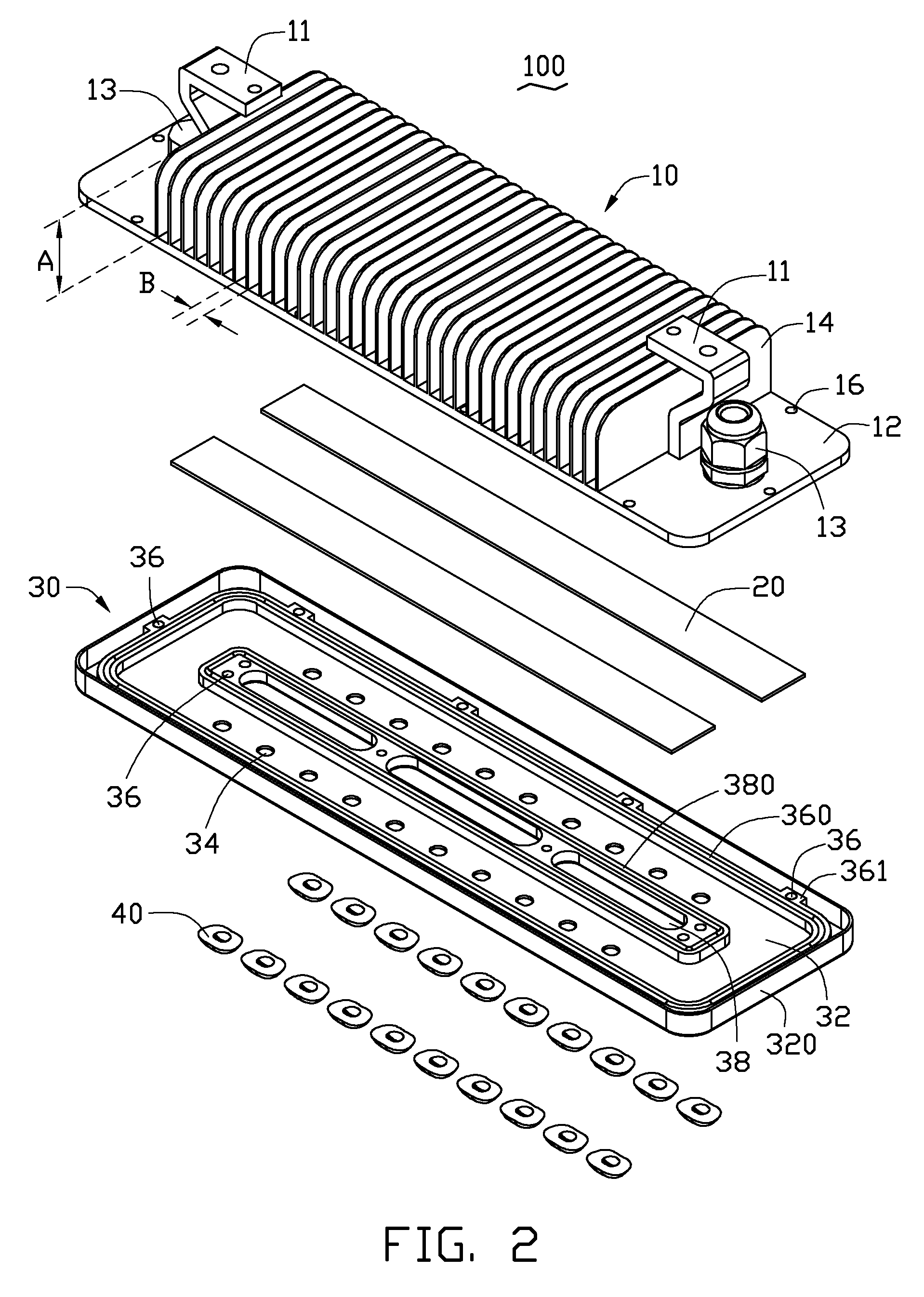
[0011]Referring to FIGS. 1-2, an LED lamp 100 in accordance with an embodiment of the present disclosure is shown. The LED lamp 100 includes a heat sink 10, two light modules 20, a lamp shell 30 and a plurality of lenses 40. The heat sink 10 is located on a top of the LED lamp 100. The two light modules 20 are fixed on a bottom of the heat sink 10. The lamp shell 30 covers the two light modules 20 and is fixed on the bottom of the heat sink 10. The lenses 40 are attached to a bottom of the lamp shell 30. The heat sink 10 is made of metal, preferably an aluminum alloy. The shell 30 and the lenses 40 are made of light permeable plastic, preferably polymethyl methacrylate (PMMA).

[0012]The heat sink 10 includes a substrate 12. The substrate 12 is a rectangular plate including a top surface, a bottom surface and a lateral surface. The lateral surface consists of a front face, a rear face, a left face and a right face. Several rectangular thin fins 14 extend upwardly from the top surface ...


PUM


Abstract

An LED lamp includes a heat sink, a lamp shell and a light module. The heat sink includes a substrate and a plurality of fins. The substrate has a top surface and a bottom surface. The lamp shell is fixed to a periphery of the substrate. The light module is received between the lamp shell and the bottom surface of the substrate of the heat sink. The substrate defines a first through-hole through the top and bottom surfaces thereof to communicate airflow channels between the fins with a space below the bottom surface of the substrate, wherein the light module is received in the space.

Description

BACKGROUND[0001]1. Technical Field[0002]The present disclosure relates to lighting apparatus, and more particularly, to an LED lamp having vertical airflow channels.[0003]2. Description of Related Art[0004]Light emitting diodes (LEDs) have many advantages, such as high luminosity, low operational voltage, low power consumption, compatibility with integrated circuits, easy driving, long term reliability, and environmental friendliness. Such advantages have promoted the wide use of LEDs as a light source. Now, LED lamps are commonly applied in lighting. However, wavelength of the light emitted by the LED lamps will have redshift if the heat generated by the LED lamp lighting device accumulates. So heat sinks for LED lamps are needed. Cooling fins are used in the heat sinks to increase heat exchange of the lamps. The cooling fins are mounted on lamp shells of the lamps. However, due to block of the lamp shells of the lamps, airflow channels defined between the cooling fins can only ext...

Claims


Application Information

Patent Timeline
Patent Type & Authority Patents(United States)
IPC IPC(8): F21V5/00F21K99/00F21S8/04F21V5/04F21V23/06F21V29/00F21V31/00F21Y101/02
CPCF21V29/225F21V29/2293F21K9/00F21V5/04F21V31/00F21S8/043F21V5/007F21V23/06F21Y2101/02F21V29/763F21V29/83F21Y2115/10
Inventor LIN, CHU-KENG
Owner FOXSEMICON INTEGRATED TECH INC
Why Eureka
Try Eureka