Boot seal for variable compression-rate engine

a variable compression rate, engine technology, applied in the direction of engine seals, engine sealing arrangements, machines/engines, etc., can solve the problems of corroding metallic components, contaminating peripheries, and evetually dispersing or scattering

Inactive Publication Date: 2015-01-20
TOYODA GOSEI CO LTD +1
View PDF34 Cites 3 Cited by
  • Summary
  • Abstract
  • Description
  • Claims
  • Application Information

AI Technical Summary

Benefits of technology

[0015]The present invention has been developed in view of the aforementioned circumstances. It is therefore an object of the present invention to provide a boot seal for “VCR” engine, boot seal which exhibits not only a higher sealing property but also better heat resistance and acid resistance.

Problems solved by technology

However, when the cylinder block and the crankcase change the relative positions between the two as in the above-described “VCR” engine, the blow-by gases or engine oils might possibly flow out from between the cylinder block and the crankcase to eventually dissipate or scatter to the outside of the “VCR” engine.
As a result, the dissipating or scattering blow-by gases or engine oils might possibly cause such problems that they might contaminate the peripheries of the “VCR” engine or they might corrode metallic component parts around the “VCR” engine.
However, general rubbers are used to make the conventional expansible / contractible members, and are weak materials against acidity and high temperatures.
On the other hand, the blow-by gases leaking out from combustion chambers exhibit acidity and high temperatures.
However, since not only fluorinated rubbers are expensive but also a boot seal for “VCR” engine has a large size relatively, using a fluorinated rubber to manufacture a boot seal for “VCR” engine has resulted in raising the material cost for manufacturing the boot seal higher.
Therefore, it is not expedient to use the conventional expansible / contractible members, which are disclosed in Japanese Unexamined Patent Publication (KOKAI) Gazette No. 2000-274,529 and Japanese Unexamined Patent Publication (KOKAI) Gazette No. 2007-78,154, as they are for making a boot seal for “VCR” engine without any modification.

Method used


Image

  • Boot seal for variable compression-rate engine
  • Boot seal for variable compression-rate engine
  • Boot seal for variable compression-rate engine

Examples


embodiment no.1

Embodiment No. 1

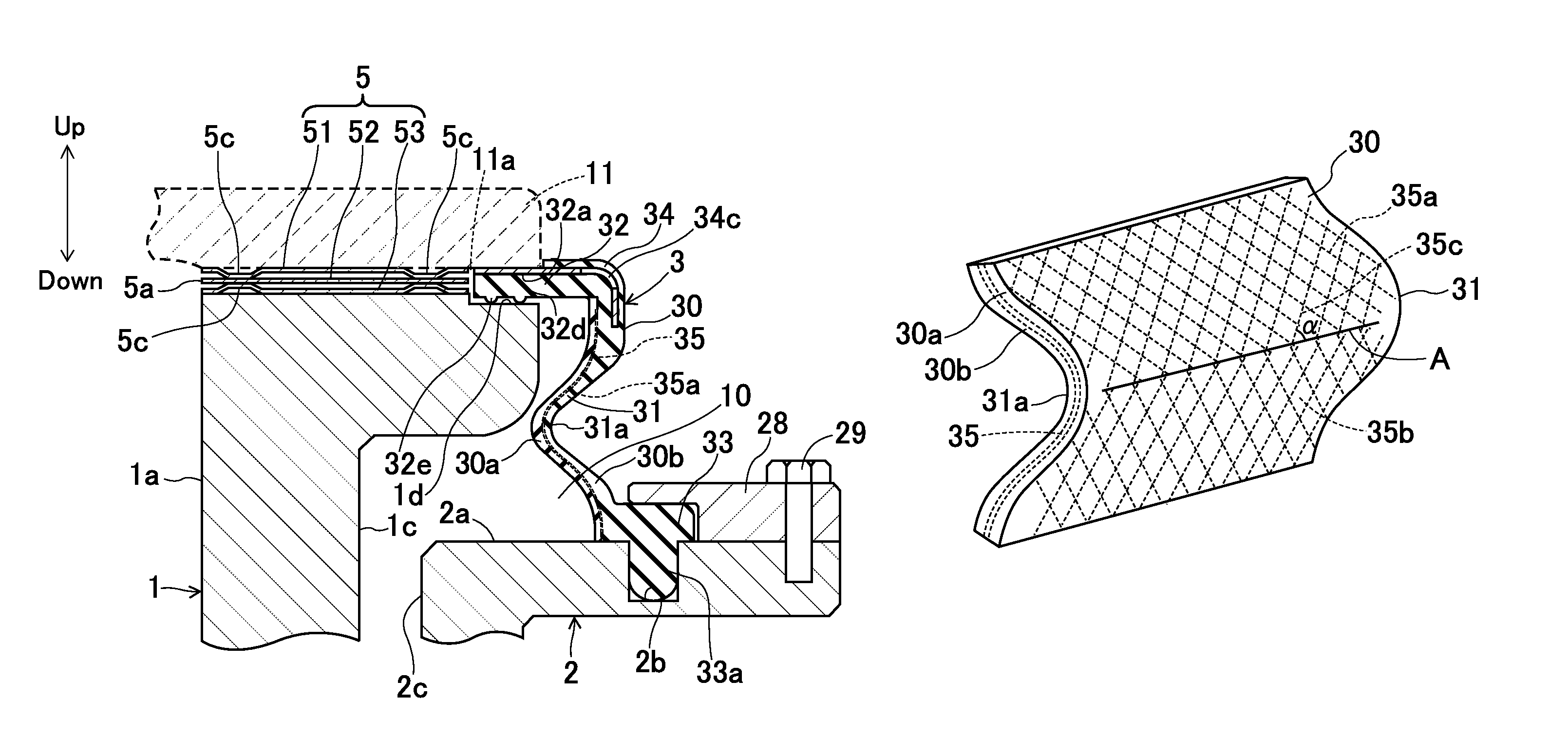
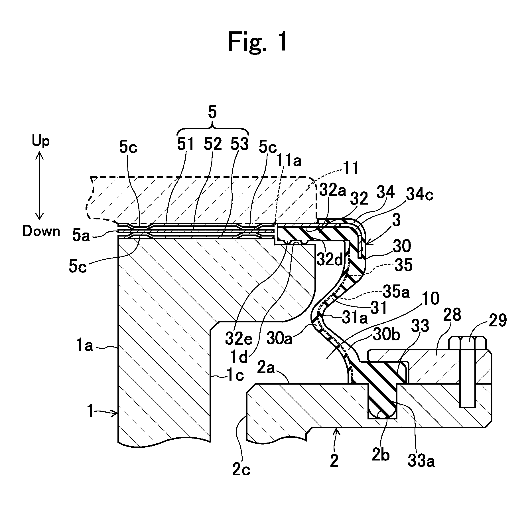
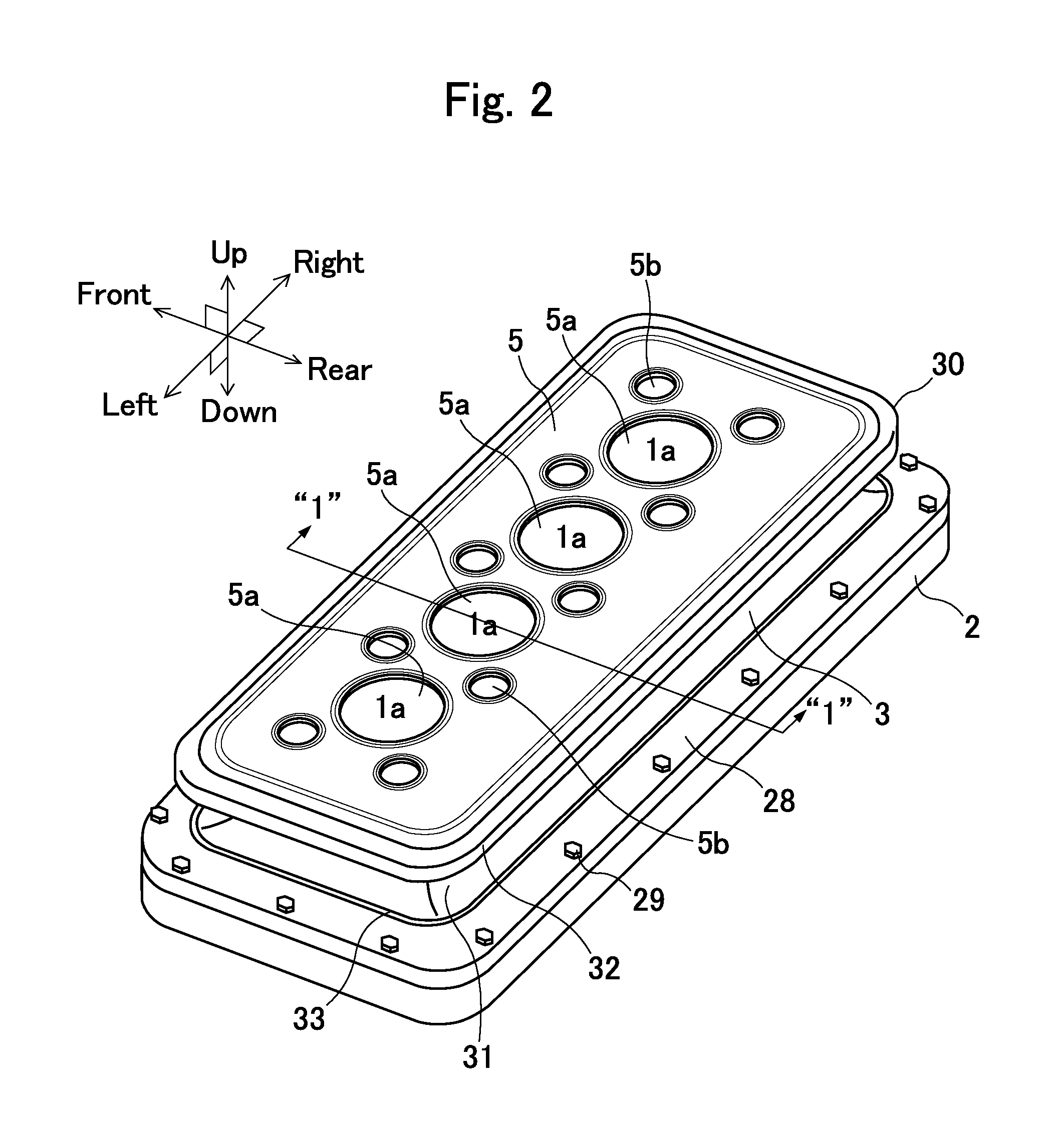
[0052]A boot seal for “VCR” engine according to Embodiment No. 1 of the present invention will be described hereinafter with reference to the accompanying drawings. Embodiment No. 1 is directed to a boot seal 3 shown in FIG. 1. As illustrated in the drawing, the boot seal 3 is mounted on a “VCR” engine to cover a clearance 10 between a cylinder block 1 and a crankcase 2 in the “VCR” engine, in which the cylinder block 1 and the crankcase 2 change their relative positions in the up / down direction in order to change the compression rate.

[0053]The cylinder block 1 takes on a rectangular shape substantially when being viewed from the top, and is put in place inside the crankcase 2 that has a box shape substantially. The cylinder block 1 is made movable with respect to the crankcase 2 in the up / down direction. The cylinder block 1 has an outer peripheral face 1c that faces an inner peripheral face 2c of the crankcase 2 by way of the clearance 10. Note that the blow-by gas...

embodiment no.2

Embodiment No. 2

[0088]As illustrated in FIG. 6, a boot seal according to Embodiment No. 2 of the present invention is distinct from the present boot seal 3 according to Embodiment No. 1 in that it comprises an annular wire stock 35b, which serves as the reinforcement member 35, instead of the net 35a. In the present boot seal according to Embodiment No. 2, the annular wire stock 35b is composed of a metallic wire, or a resinous filament or fiber. The metallic wire can be made of stainless steel (SUS (as per Japanese Industrial Standard (JIS)), or Cu. The resinous filament or fiber can be made of aromatic polyamide or polyphenylene sulfide (or PPS). Note that aromatic polyamide or PPS exhibits a melting point that is higher than the temperature for vulcanizing the materials making the boot-seal element 30. Both wire and filament or fiber can be provided with irregularities at predetermined intervals in the extending direction. When the wire stock 35b is made of a resinous filament or...

embodiment no.3

Embodiment No. 3

[0093]As illustrated in FIG. 7, a boot seal according to Embodiment No. 3 of the present invention is distinct from the present boot seal 3 according to Embodiment No. 1 in that it comprises a reinforcement member 35 that is disposed partially in the deformer 31 of the boot-seal element 30 alone. That is, the reinforcement member 35 is put in place in the root 31a of the deformer 31 of the boot-seal element 30 as well as around the top and bottom peripheries of the root 31a, but is not put in place at all in the cylinder-block fitting 32 and crankcase fitting 33 that make the top and bottom of the boot-seal element 30. A net 35a, which is similar to that of the present boot seal 3 according to Embodiment No. 1, is used to make the reinforcement member 35. The present boot seal according to Embodiment No. 3 can be manufactured as shown in FIGS. 4A through 4E, namely, by the same process as that for manufacturing the present boot seal 3 according to Embodiment No. 1.

[0...


PUM


Abstract

A boot seal for variable compression-rate engine includes a boot-seal element, and a reinforcement member. The boot-seal element includes an inner layer, and an outer layer. The inner layer is disposed on the inner face of the boot-seal element, and is composed of a fluorinated rubber. The outer layer is disposed on a more outer side of the boot-seal element than is the inner layer. Moreover, the boot-seal element is formed in a circumferentially developed state so as to have circumferential ends, and is then completed by joining the circumferential ends with each other. Thus, the boot-seal element makes an elastically deformable cylindrical bellows shape having a root that dents inward diametrically. In addition, the reinforcement member is disposed in the root of the cylindrical bellows-shaped boot-seal element at least.

Description

INCORPORATION BY REFERENCE[0001]The present invention is based on Japanese Patent Application No. 2011-70,002, filed on Mar. 28, 2011, the entire contents of which are incorporated herein by reference.BACKGROUND OF THE INVENTION[0002]1. Field of the Invention[0003]The present invention relates to a boot seal for variable compression-rate engine.[0004]2. Description of the Related Art[0005]An engine has been known, engine into which the fuel-air mixture is supplied while changing the compression rate in compliance with the traveling conditions of vehicle (that is, a so-called variable compression-rate engine (being abbreviated to as “VCR” engine hereinafter)). The “VCR” engine makes it possible to retrieve higher torques by heightening the compression rate at the time of lower loads, and makes it possible to inhibit knocking from occurring by lowering the compression rate at the time of higher loads.[0006]In such a “VCR” engine, at least one of a cylinder block and a crankcase is mov...

Claims


Application Information

Patent Timeline
Patent Type & Authority Patents(United States)
IPC IPC(8): F16J3/00F02B75/04F16J3/04
CPCF16J3/042F16J3/041F02B75/041
Inventor MITSUI, KENICHIOTA, KATSUHISAITOU, KAORU
Owner TOYODA GOSEI CO LTD
Why Eureka
Try Eureka