Seal devices for filters

a filter and sealing technology, applied in the field of filters, can solve the problems of increasing the likelihood that contaminated fluid can bypass the filter, and the seal is more difficult to provide a full sealing relationship, and achieves the effect of sufficient resiliency and flexibility

Active Publication Date: 2015-02-24
PARKER INTANGIBLES LLC
View PDF20 Cites 6 Cited by
  • Summary
  • Abstract
  • Description
  • Claims
  • Application Information

AI Technical Summary

Benefits of technology

[0005]In one aspect, the invention provides a filter element. The filter element comprises a first end cap and a second end cap. The filter element further comprises a tubular ring of filter media, which extends between the first and second end caps and around a longitudinal axis. The first end cap carries a gasket, which has an annular sealing flange and an annular base portion. In a first embodiment, the annular sealing flange is spaced radially outside the annular base portion and an outer peripheral surface of the end cap. In an alternative embodiment, the annular sealing flange is spaced radially inside the annular base portion and an inner peripheral surface of the end cap. In either embodiment, the gasket is elastomeric with sufficient resiliency and flexibility to conform and seal to a non-round opening with up to at least 0.01 inch, more preferably up to 0.1 inch, and most preferably 0.25 inch in a diameter variance from round. The gasket also has sufficient resiliency and flexibility to conform to generally round openings having diameters that are up to 0.125 inches outside a design diameter, as well as to surfaces having a surface roughness of up to 90 micro inches. This sealing ability allows a filter to be sealed to imperfectly manufactured sealing surfaces, such as machined or stamped openings in filter housings.
[0006]In a preferred embodiment, the annular sealing flange extends at a canted angle of between 10 and 85 degrees relative to the longitudinal axis of the filter. The annular sealing portion thus defines an annular pocket with the annular base portion. In a more preferred embodiment, the gasket has an outer diameter with a design toleranced variance of greater than 1% and up to at least 5%, thus allowing design and lower cost flexibility to the gasket. The gasket is formed from a seal material having a Shore A durometer of between 30 and 80, and an elongation of between 100 and 400. The seal material may be made from a suitable sealing material such as at least one of buna-n (nitrile), fluoropolymer, silicone, fluorosilicone, and EPR (ethylene propylene rubber), although other suitable seal materials are contemplated.
[0012]In another aspect, the invention provides a filter system. The filter system includes filter element and a housing with an inlet and an outlet, and fluid flows from the inlet to the outlet. The housing further comprises a radial seal housing surface. The filter element comprises a first end cap and a second end cap. The filter element further comprises a tubular ring of filter media, which extends between the first and second end caps and around a longitudinal axis. The first end cap carries a gasket, which has an annular sealing flange and an annular base portion. In a first embodiment, the annular sealing flange is spaced radially outside the annular base portion and an outer peripheral surface of the end cap. In an alternative embodiment, the annular sealing flange is spaced radially inside the annular base portion and an inner peripheral surface of the end cap. In either embodiment, the gasket is elastomeric with sufficient resiliency and flexibility to conform and seal to a non-round opening with up to at least 0.01 inch, more preferably up to 0.1 inch, and most preferably 0.25 inches in a diameter variance from round. The gasket also has sufficient resiliency and flexibility to conform to generally round openings having diameters that are up to 0.125 inches outside a design diameter, as well as to surfaces having a surface roughness of up to 90 micro inches. This sealing ability allows a filter to be sealed to imperfectly manufactured sealing surfaces, such as machined or stamped openings in the filter housing.

Problems solved by technology

Fluid streams such as liquid flows and gaseous flows (e.g. air flows) often carry particulates that are often undesirable contaminants entrained in the fluid stream.
Often, an imperfectly manufactured filter housing or pipe will have a sealing surface that is out of round or out of tolerance, thus making it more difficult for the seal to provide a full sealing relationship, and increasing the likelihood that contaminated fluid can bypass the filter.
However, if that is not done, then a problem exists as typical O-ring gaskets can have sealing problems and therefore allow some leakage if the sealing surface is even 0.0005 inches out of round, or has an actual diameter even 0.010 greater than a design diameter.

Method used


Image

  • Seal devices for filters
  • Seal devices for filters
  • Seal devices for filters

Examples


Embodiment Construction

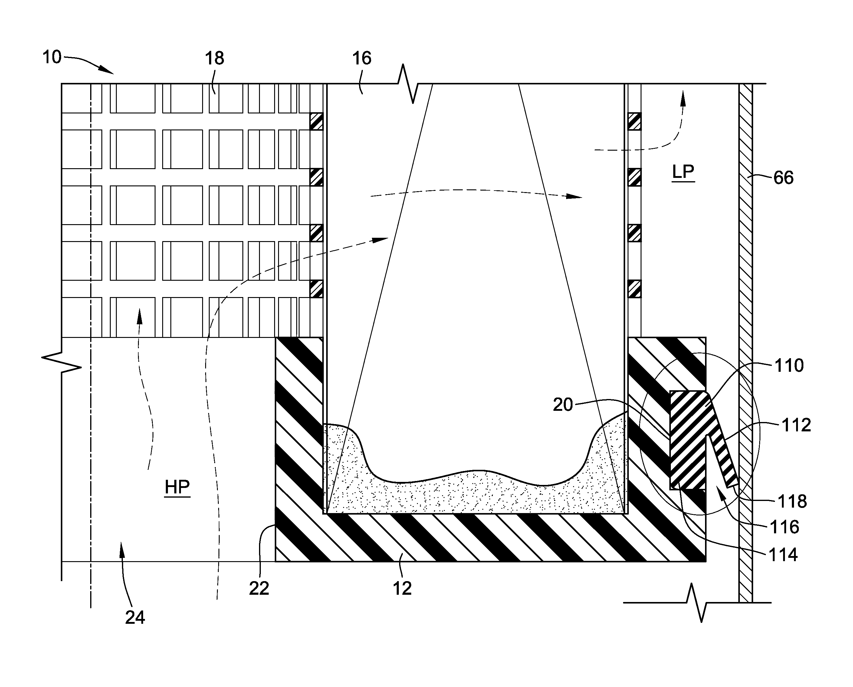
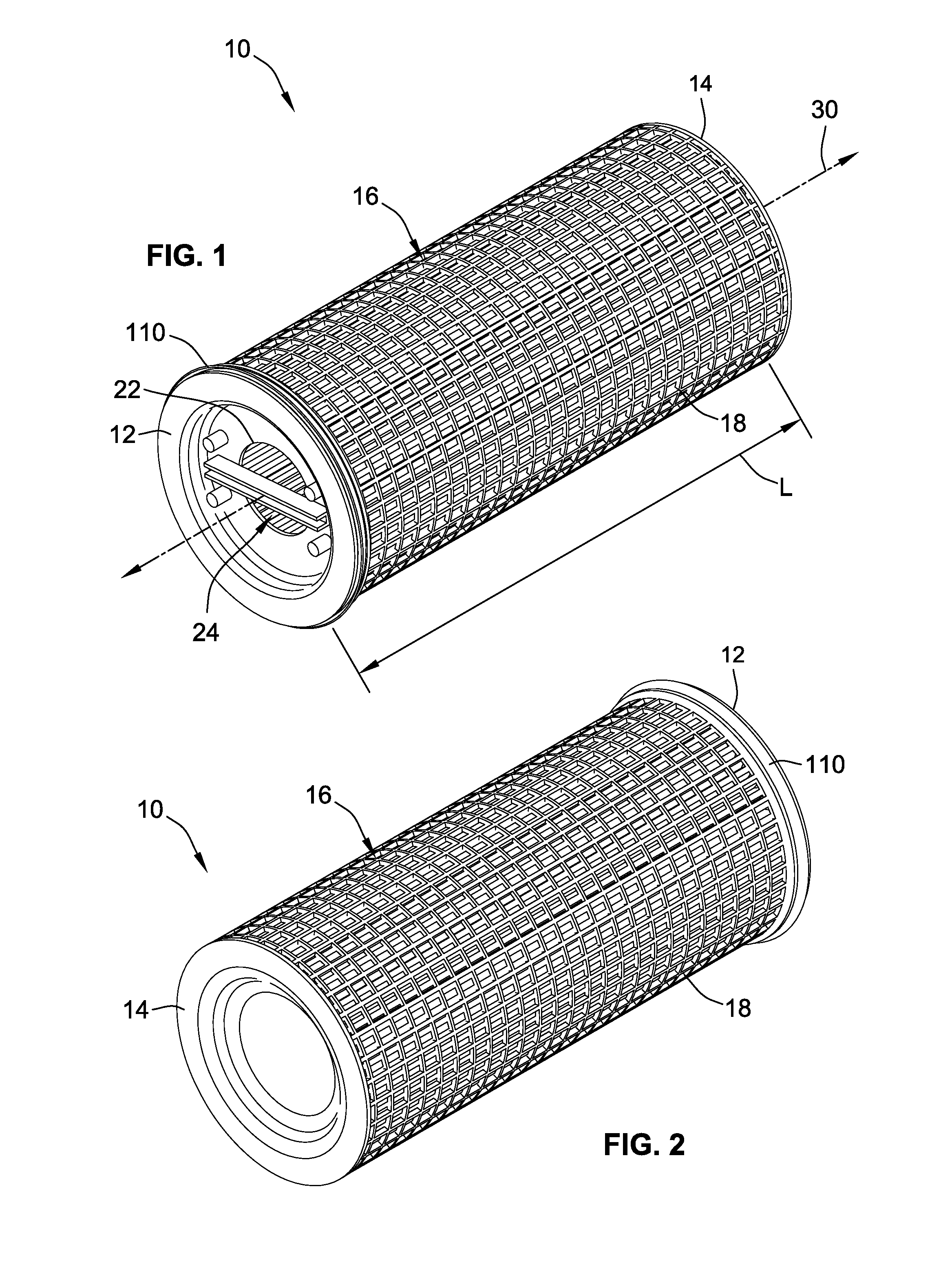
[0028]With reference to FIGS. 1 and 2, a filter 10 having seal to accommodate non-round openings is provided (accommodating openings with up to at least 0.01 inch, more preferably up to 0.1 inch, and most preferably 0.25 inches in a diameter variance from round), which may take the form of a chevron seal 110 as discussed in embodiments below. The filter 10 includes an open end cap 12 and a closed end cap 14. Filter media 16 extends between the end caps 12 and 14 and around a longitudinal axis 30 such that the filter 10 is generally hollow and defines an inner cavity 24. In a preferred embodiment, the filter media 16 is a pleated filter media, although other types of filter media are contemplated such as depth media for example. The filter 10 may further include a support wrapper 18, which is made of a suitable porous somewhat-rigid material. The open end cap 12 defines a central flow opening 22 and an outwardly opening annular groove 20 (shown in FIG. 8), which carries the chevron s...


PUM

PropertyMeasurementUnit
diameteraaaaaaaaaa
diameteraaaaaaaaaa
diameteraaaaaaaaaa

Abstract

A filter element having an end cap is provided with a seal that can better accommodate non-round holes. The seal may be a chevron type seal and / or other similar seal having a sealing flange for forming a radial seal. Methods of replacing a filter having an O-ring gasket to improve upon sealing are provided as well as filtration systems employing the filter element.

Description

FIELD OF THE INVENTION[0001]This invention generally relates to filters, and in particular to filters having seals, and methods for installing the same.BACKGROUND OF THE INVENTION[0002]Fluid streams such as liquid flows and gaseous flows (e.g. air flows) often carry particulates that are often undesirable contaminants entrained in the fluid stream. Filters are commonly employed to remove some or all of the particulates from the fluid stream.[0003]Seals such as o-rings are often provided to seal the filter to a surface of a filter housing, or to an inlet or outlet pipe, which carries the contaminated fluid or gas into or out of the filter. This sealing relationship helps prevent unfiltered fluid from bypassing the filter. Often, an imperfectly manufactured filter housing or pipe will have a sealing surface that is out of round or out of tolerance, thus making it more difficult for the seal to provide a full sealing relationship, and increasing the likelihood that contaminated fluid c...

Claims


Application Information

Patent Timeline
Patent Type & Authority Patents(United States)
IPC IPC(8): B01D46/00B01D29/21B01D29/23B01D29/52B01D46/24
CPCB01D46/2403B01D29/21B01D29/232B01D29/52B01D2271/027B01D2201/0476B01D2201/295B01D2201/34Y10T29/4973
Inventor BURNS, DAVID J.CLOUD, DANIEL M.JONES, ARTIMUS CHARLESBOSWELL, TYLER GLENN
Owner PARKER INTANGIBLES LLC
Why Eureka
Try Eureka