Self-rejecting automotive harness connector

a technology of automotive harness and electronic connector, which is applied in the direction of coupling device connection, coupling device engagement/disengagement, incorrect coupling prevention, etc., and can solve the problems of affecting the electrical interconnection properties of the cable, and affecting the reliability of the cabl

Active Publication Date: 2015-03-03
JAE OREGON
View PDF54 Cites 88 Cited by
  • Summary
  • Abstract
  • Description
  • Claims
  • Application Information

AI Technical Summary

Benefits of technology

[0054]A connector assembly in accordance with the invention accomplishes CPA by using an internal component referred to as a slider which is driven by a compressive member, such as a helical spring, so the slider will release at a predetermined fully mated engagement. So released, the slider is then driven automatically to insert a blocking beam directly behind a previously engaged latching beam, so that the operative space needed for unlatch is blocked. The latch is now trapped in its locked state and the cable-side connector cannot disengage from its complementary plug-side receptacle. The connector assembly is advantageous, in one respect, over prior art connectors in view of this secondary locking element reinforcing these cantilever features against becoming unlatched, and specifically, advantageous over prior art latching connectors lacking cantilevered means of locking into complementary features.

Problems solved by technology

Yet these design features are rarely fool-proof and invite an assembly error in which a partially or incompletely mated connector passes an assessment of its electrical interconnectivity while the physical locking features are not completely engaged and fully actuated.
The danger posed by a positive reading of electrical continuity plus a cursory visual inspection failing to detect that an installment is in fact incomplete is that subsequent vibration, shocks, and atmospheric oxidation in service can disconnect the cable or substantially degrade its electrical interconnect properties such that a mission-critical safety device fails to receive an electrically transmitted signal.
Insertion of the first housing into the second housing causes a latching mechanism located within the assembled first and second housings to latch the housings together so that they cannot be readily disengaged.
There is no feature that confirms an efficacious and reliable locked interconnect condition to the user.
Release from the locked state cannot be obtained by pulling the button housing away from the receptacle.
The connector therefore does not provide a more convenient single motion mechanism with automated triggering of the CPA, or self-rejection.
The connector does not offer automatic snap-in of the secondary lock and does not offer self-rejection.
This device does not offer self-rejection from an incomplete mating attempt.
This device has no cantilever beam latches and no automatic locking or blocking beams able to prevent disconnect, and no effective mechanism for self-rejecting from an incomplete mating attempt.
Furthermore, the connector does not provide a mechanism for either visual indication of, or self-rejection from an incomplete mating.
U.S. Pat. Appin. Publ. No. 2010 / 0233897(A1) entitled “Electrical Connector Assembly Having Connector Position Assurance Device” by Seo et al., describes a device having a manually actuated secondary lock, but does not offer automatic snap-in of the secondary lock or self-rejection.
The connector does not offer automatic snap-in of the secondary lock or self-rejection.
The connector does not provide a secondary locking of previously engaged latches.
Furthermore, the connector of Nakamura does not provide a mechanism for either visual indication of, or self-rejection from an incomplete mating attempt.

Method used


Image

  • Self-rejecting automotive harness connector
  • Self-rejecting automotive harness connector
  • Self-rejecting automotive harness connector

Examples


Embodiment Construction

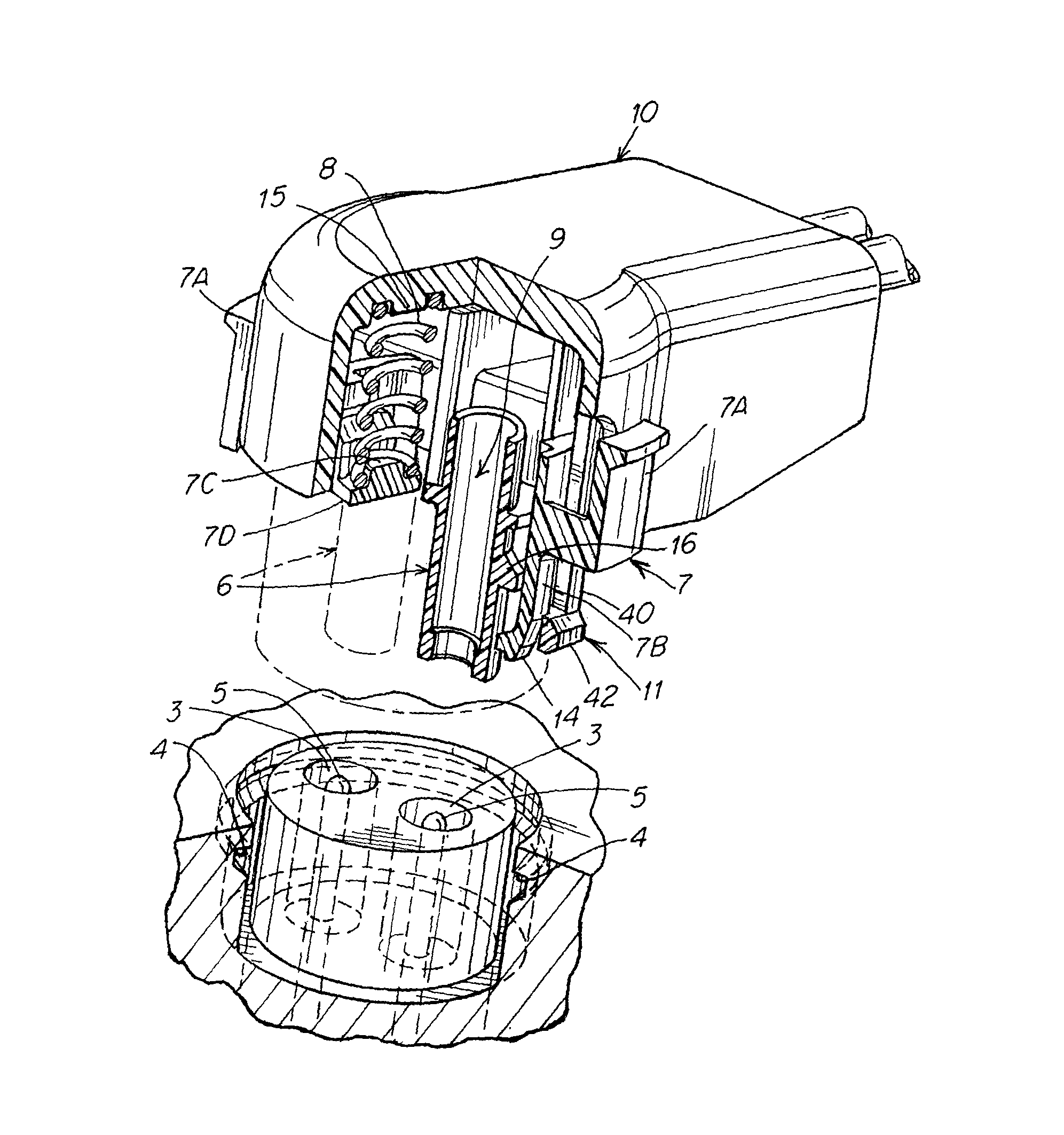
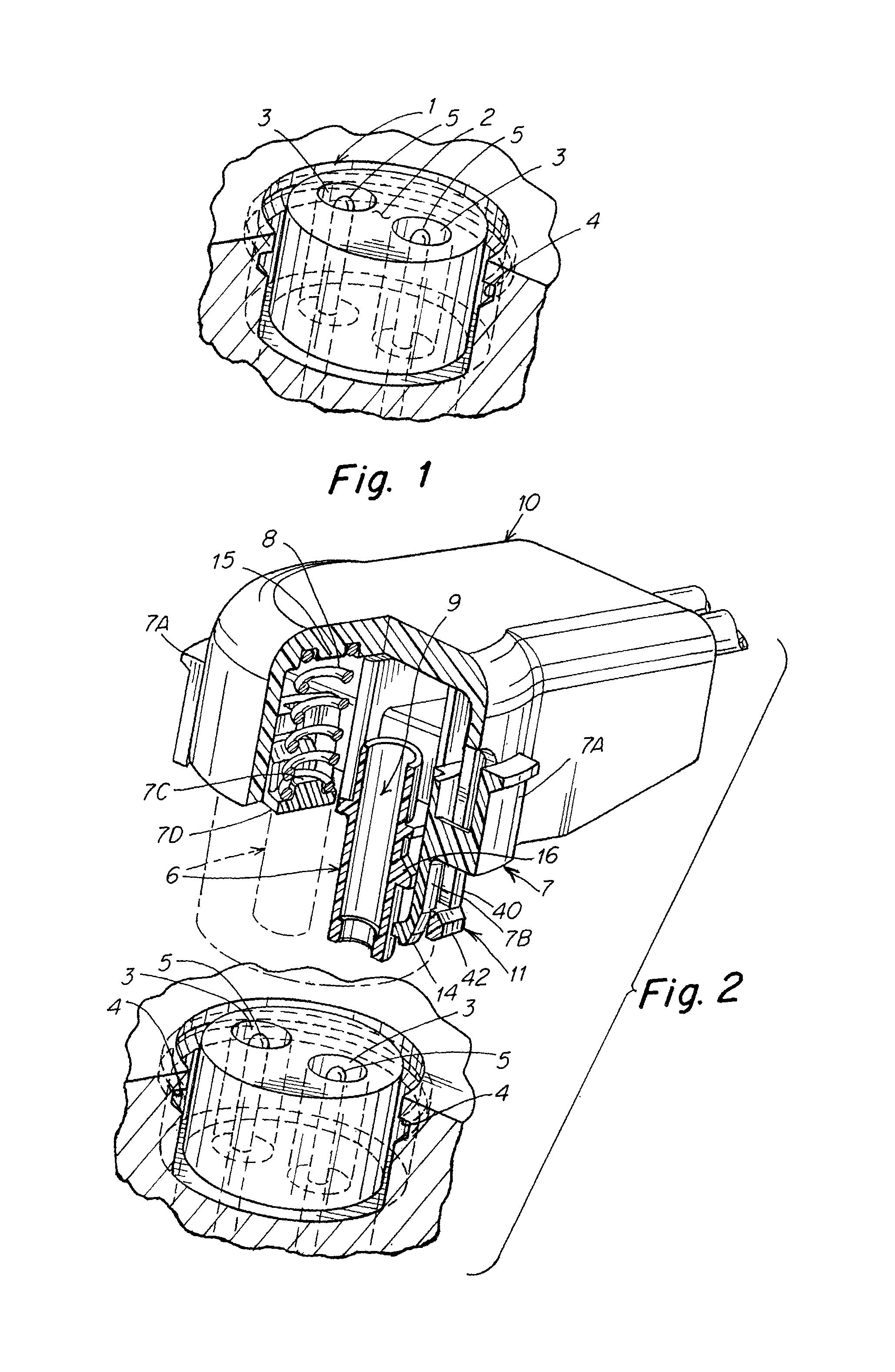
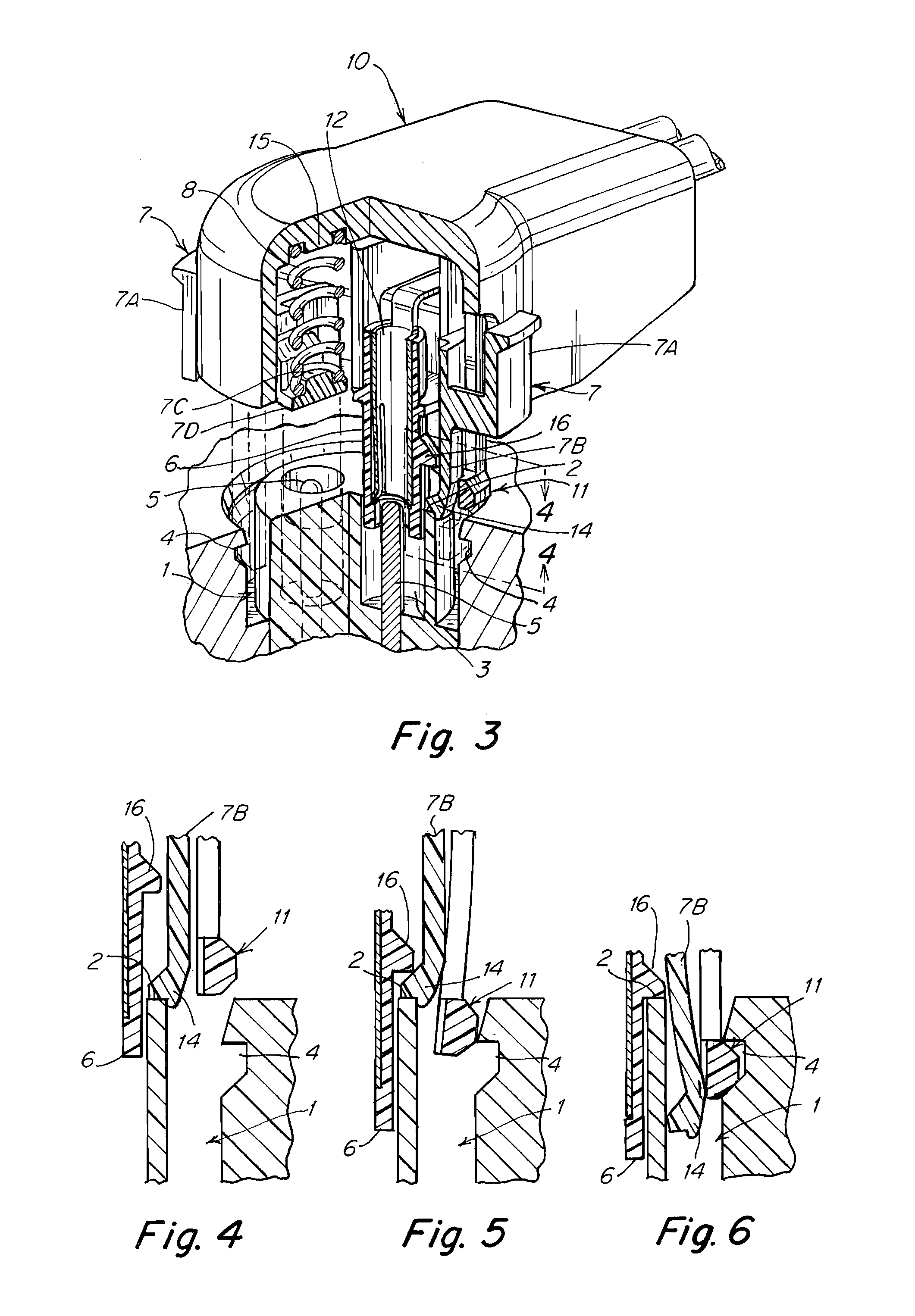
[0076]Referring to the accompanying drawings wherein the same reference numbers refer to the same or similar elements, FIG. 1 shows a broken-view partial cross section of a typical, generally circular receptacle as an example of a receptacle to which the inventive connector assembly is designed to mate in a highly dependable and reliable manner. This receptacle is also referred to as a “plug connector” herein and the inventive connector assembly is also referred to as a “receptacle connector” herein. Certain features of the receptacle are controlled by industry standards and are outside the scope of this invention. Generally, the receptacle offers a substantially annular cavity 1, an outward facing bulkhead surface 2 of a cylindrical form inside the cavity 1 and that is generally perpendicular to the direction of line of action of the mating motion of the connector assembly to the receptacle, and a plurality of terminal-containing apertures 3 within which reside a set of electrical ...


PUM


Abstract

A plug-in connector for connecting to a receptacle including a housing including fins, at least one electrically conductive terminal at least partly situated in the housing and defining a mating axis and a mating direction, cantilevered locking beams arranged in the housing, a slider slidingly coupled to the housing and including blocking beams extending in the mating direction, a compressive member arranged to urge the slider outward away from the housing in the mating direction. The fins are situated to engage with the blocking beams during an initial stage of relative movement between the housing and the slider against a bias of the compressive member and allow inward deflection of the locking beams. The blocking beams are configured to prevent inward deflection of the locking beams after a final stage of the relative movement between the housing and the slider.

Description

CROSS-REFERENCE TO RELATED APPLICATION[0001]This application claims priority under 35 U.S.C. §119(e) of U.S. provisional patent application Ser. No. 61 / 914,829 filed Dec. 11, 2013, which is incorporated by reference herein.BACKGROUND OF THE INVENTION[0002]1. Field of the Invention[0003]The present invention relates generally to internal structures and mechanisms of an electronic connector of a cable. More particularly, the present invention relates to internal structures and mechanisms of an electronic controller of a cable used to electronically activate mission-critical safety devices in vehicles.[0004]The present invention also relates to electric connectors for specific cables, namely, those that have a headshell deploying positive locking means to intermate the cable conductors to those in a receptacle on a device or in a receptacle on another cable assembly, with the locking means being substantially permanent or requiring a deliberate actuation of at least one mechanical comp...

Claims


Application Information

Patent Timeline
Patent Type & Authority Patents(United States)
IPC IPC(8): H01R13/627H01R13/64H01R43/26
CPCH01R13/64H01R13/6271H01R43/26H01R13/6273H01R13/635H01R13/639H01R13/641
Inventor KENNEDY, ADAMOKUDA, KATSUMASALETOURNEAU, GUYDAMODHARAN, KASTHURI SANKAR
Owner JAE OREGON
Why Eureka
Try Eureka