Battery assembling device

a battery and assembly technology, applied in the field of batteries assembling devices, can solve the problems of time-consuming, inconvenient and time-consuming, and the need for a lot of battery modules in an electrical vehicle, and achieve the effect of quick and easy assembly of batteries

Active Publication Date: 2015-03-03
AUTOMOTIVE RES & TESTING CENT
View PDF5 Cites 2 Cited by
  • Summary
  • Abstract
  • Description
  • Claims
  • Application Information

AI Technical Summary

Benefits of technology

[0007]The main objective of the invention is to provide a battery assembling device that can quickly and easily assemble batteries.
[0008]A battery assembling device has two brackets and an assembling unit. The brackets abut each other and can be securely mounted around two battery units. The assembling unit has a quick-release housing and two clamps. The quick-release housing has two electrode holes. The clamps are respectively mounted in the electrode holes and each clamp has two opposite threaded inner surfaces. The battery units can be bundled by the brackets in advance to form regular battery modules. Because the assembling unit is easily and quickly connected with the battery modules, the assembling of a cell of an electrical vehicle is greatly convenient and fast.

Problems solved by technology

However, lots of battery modules are required in an electrical vehicle.
Assembling the battery modules one by one is time-consuming.
Moreover, the protrusions 92 of each bracket 90 have to be rotated in a specific direction to be connected with the recesses 93 of another bracket 90, but this is inconvenient and time-consuming.

Method used


Image

  • Battery assembling device
  • Battery assembling device
  • Battery assembling device

Examples


first embodiment

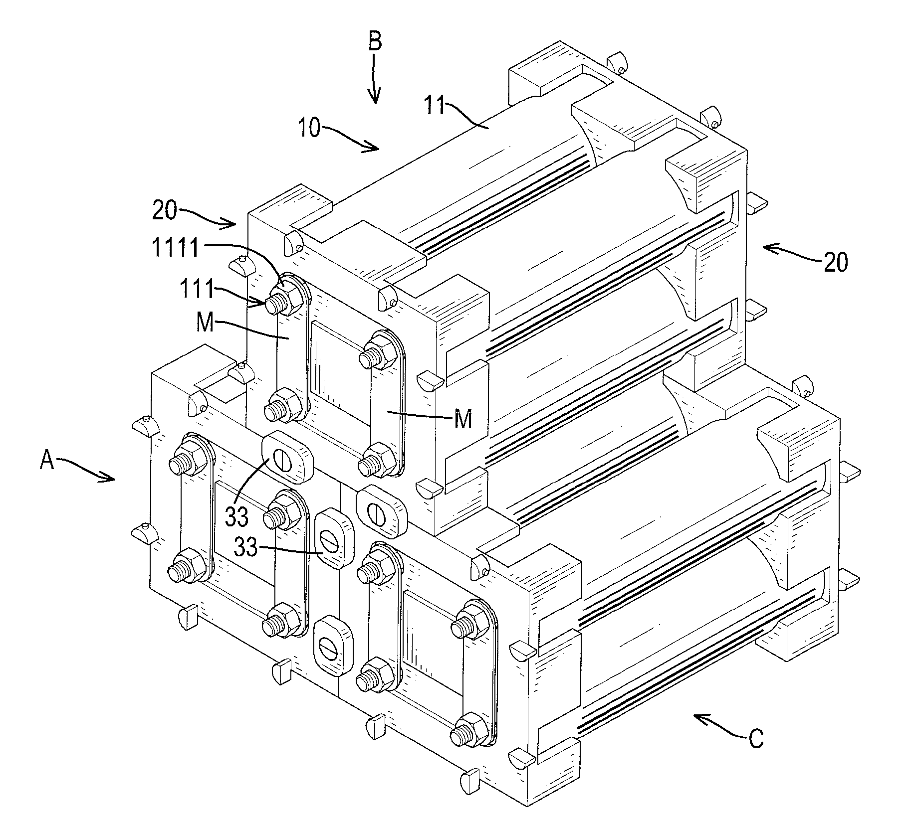
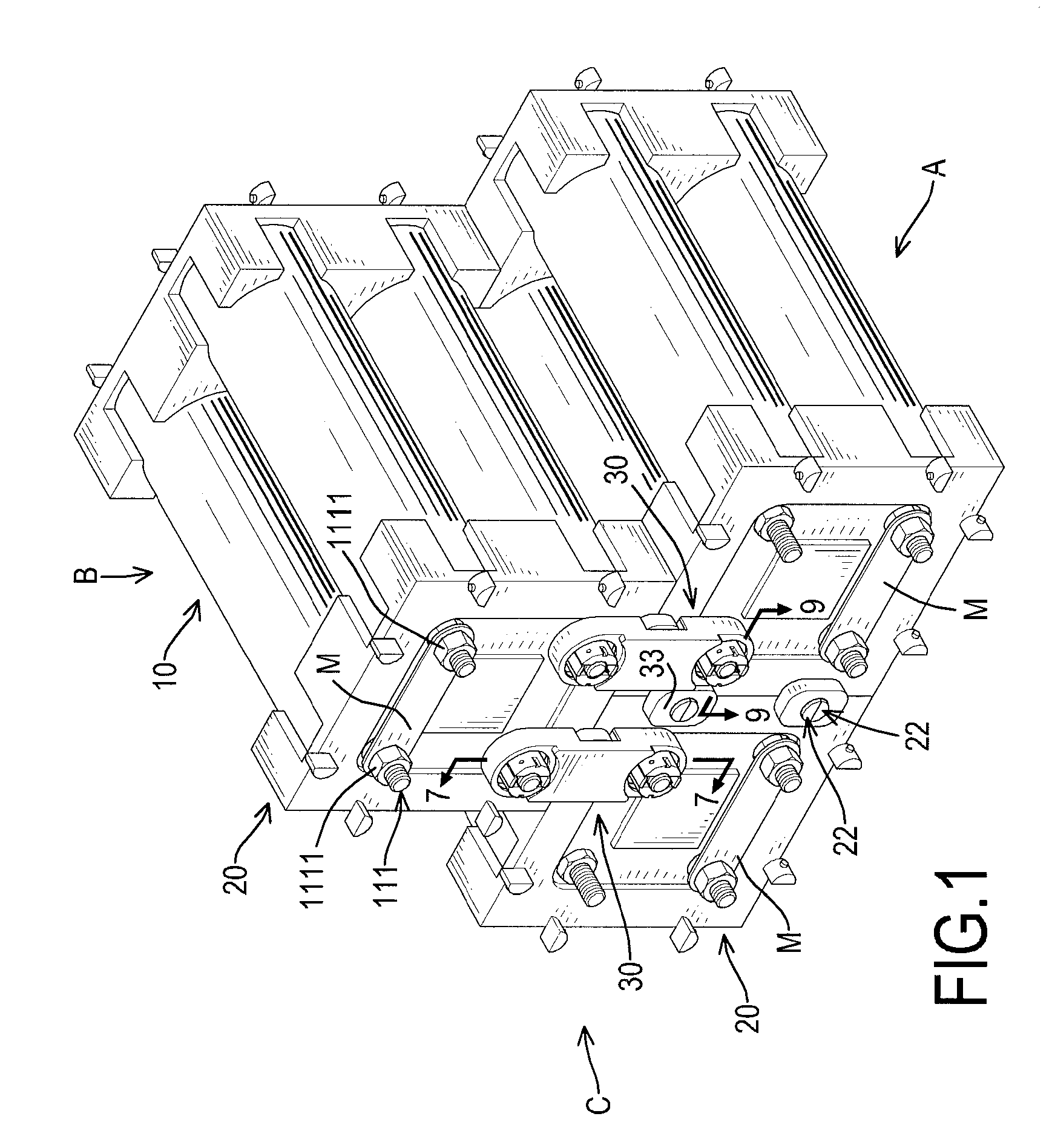
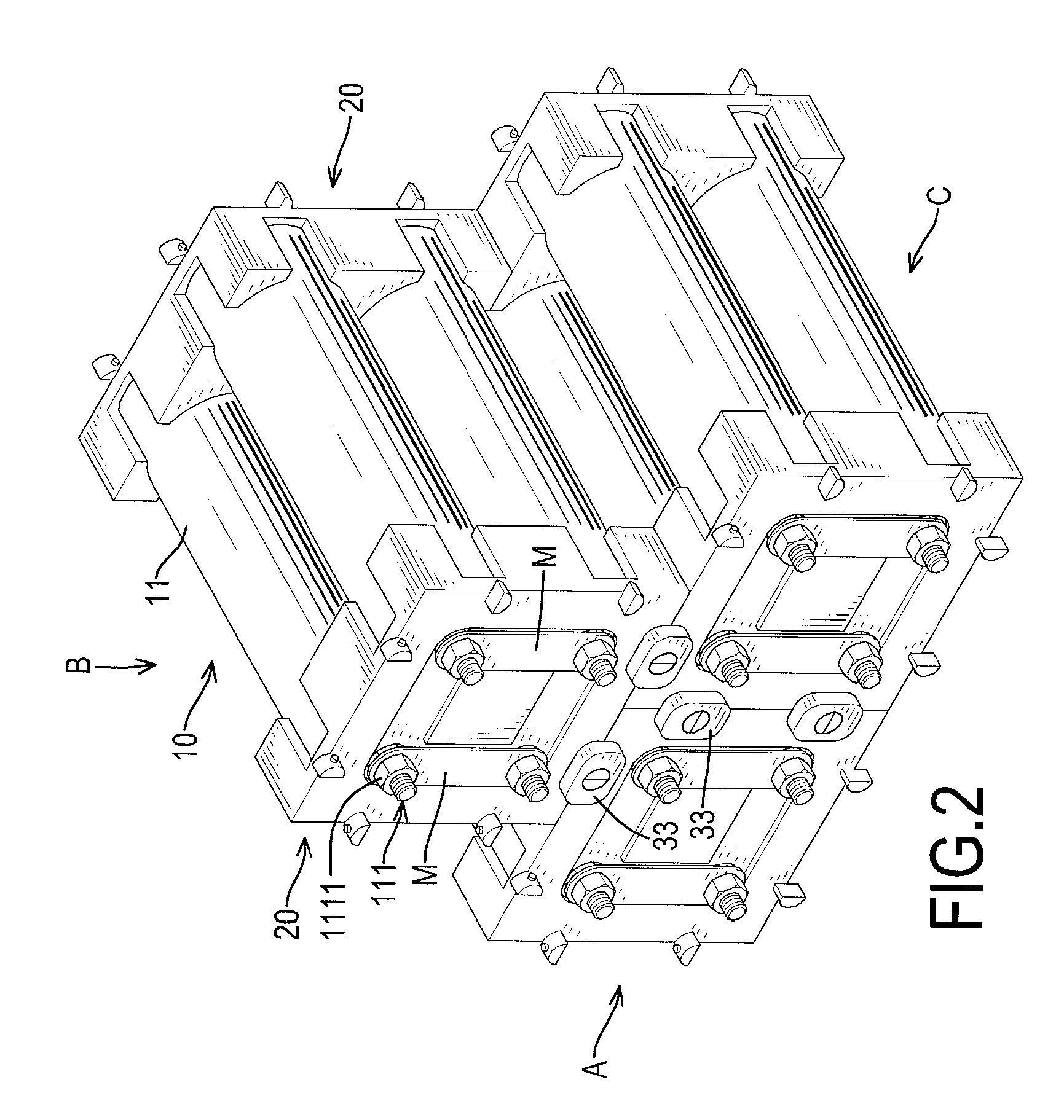
[0024]With reference to FIGS. 1 and 2, a battery assembling device in accordance with the present invention has at least two brackets 20 and at least one assembling unit 30 and is connected with multiple battery units 10 to form an in-series cell.

[0025]Preferably, the in-series cell has three battery modules and two assembling units 30. Each battery module has one battery unit 10, two brackets 20 and multiple metal sheets M.

[0026]With further reference to FIG. 7, each battery unit 10 has multiple batteries 11 arranged as a matrix. Preferably, each battery unit 10 has four batteries 11. Each battery 11 has two opposite sides and two electrodes 111. The electrodes 111 of each battery 11 respectively protrude from the opposite sides of the battery 11 and each electrode 111 has a nut section 1111.

[0027]Number of the battery 11 of each battery unit 10 is variable, such as six or eight batteries 11. Moreover, each battery module can be assembled in advance for further assembling with the ...

second embodiment

[0063]Each bracket 20A is mounted securely on one side of a corresponding battery unit 10A. Each battery unit 10A has four batteries 11A. Similarly, with the metal sheets M electrically abutting the electrodes 111A, the batteries 11A of each battery module can be connected in series. However, the assembling units 30A of the second embodiment make the battery modules connected in parallel.

[0064]Take one assembling unit 30A for example, with reference to FIGS. 10 to 12, the parallel connecting housing 34A spans the upper two battery modules and has a shell 341A and a conductive plate 342A.

[0065]The shell 341A of the parallel connecting housing 34A has an electrode hole 3411A formed through the shell 341A of the parallel connecting housing 34A.

[0066]The conductive plate 342A is mounted securely in the shell 341A of the parallel connecting housing 34A and has a protrusion 3421A. The protrusion 3421A of the parallel connecting housing 34A protrudes out from the shell 341A of the parallel...


PUM

PropertyMeasurementUnit
metallic conductiveaaaaaaaaaa
conductiveaaaaaaaaaa
diameteraaaaaaaaaa

Abstract

A battery assembling device has two brackets and an assembling unit. The brackets abut each other and can be securely mounted around two battery units. The assembling unit has a quick-release housing and two clamps. The quick-release housing has two electrode holes. The clamps are respectively mounted in the electrode holes and each clamp has two opposite threaded inner surfaces. The battery units can be bundled by the brackets in advance to form regular battery modules. Because the assembling unit is easily and quickly connected with the battery modules, the assembling of a cell of an electrical vehicle is greatly convenient and fast.

Description

BACKGROUND OF THE INVENTION[0001]1. Field of the Invention[0002]The present invention relates to a battery assembling device, and more particularly to a battery assembling device that can quickly and easily assemble batteries.[0003]2. Description of Related Art[0004]Two opposite sides of a battery for an electrical vehicle are respectively covered by two brackets to form a battery module. With reference to FIG. 14, each conventional bracket 90 has four edges, a bracket hole 91, multiple protrusions 92 and multiple recesses 93. The bracket hole 91 is formed through the bracket 90 and can be inserted by an electrode of a battery. The protrusions 92 and the recesses 93 of each bracket 90 are formed on the edges of the bracket 90 at intervals. Two of the protrusions 92 of each bracket 90 can be respectively mounted in two of the recesses 93 of the other bracket 90. Accordingly, two brackets 90 can be assembled and multiple battery modules can be connected securely to form a cell that is...

Claims


Application Information

Patent Timeline
Patent Type & Authority Patents(United States)
IPC IPC(8): H01M6/42H01M50/204H01M50/271H01M50/502
CPCY02E60/10H01M50/502H01M50/271H01M50/204
Inventor JIANG, CHENG-SHUNHSU, JIA-SING
Owner AUTOMOTIVE RES & TESTING CENT
Why Eureka
Try Eureka