
Fastening structure, electronic assembly and operating method of fastening structure

a technology of fastening structure and electronic assembly, which is applied in the direction of recording information storage, record carrier construction details, instruments, etc., can solve the problems of difficulty in screw-locking, process may take a certain amount of time, and the time required to turn off the device for maintenance may thus increase significantly, so as to achieve quick switching of the connector and simple fastening structure

Active Publication Date: 2019-01-01
WISTRON CORP
View PDF8 Cites 2 Cited by
  • Summary
  • Abstract
  • Description
  • Claims
  • Application Information

AI Technical Summary

Benefits of technology

Enables quick and easy assembly of connectors, reduces assembly time and costs, and prevents stress concentration, thereby increasing the lifespan of connectors by allowing flexible movement and avoiding structural damage during maintenance or operation.

Problems solved by technology

Such process may take a certain amount of time, and the time required to turn off the device for maintenance may thus increase significantly.
If the case is a server case, the frame is thin, and the height between levels in the frame is short, so no matter a computer or a server is installed, the case may be filled with various components, such as interface cards, hard drives, and power wires, and may cause difficulties on screw-locking.
Sometimes the screws may even be detached during screw-locking and the screws may be lost.
Thus, the operation of the storage device or the vibration caused by maintenance or movement may result in structural damage at the stress concentration part, and the connector may consequently be damaged.

Method used


Image

  • Fastening structure, electronic assembly and operating method of fastening structure
  • Fastening structure, electronic assembly and operating method of fastening structure
  • Fastening structure, electronic assembly and operating method of fastening structure

Examples


Embodiment Construction

[0019]Reference will now be made in detail to the present preferred embodiments of the present disclosure, examples of which are illustrated in the accompanying drawings. Wherever possible, the same reference numbers are used in the drawings and the description to refer to the same or like parts.

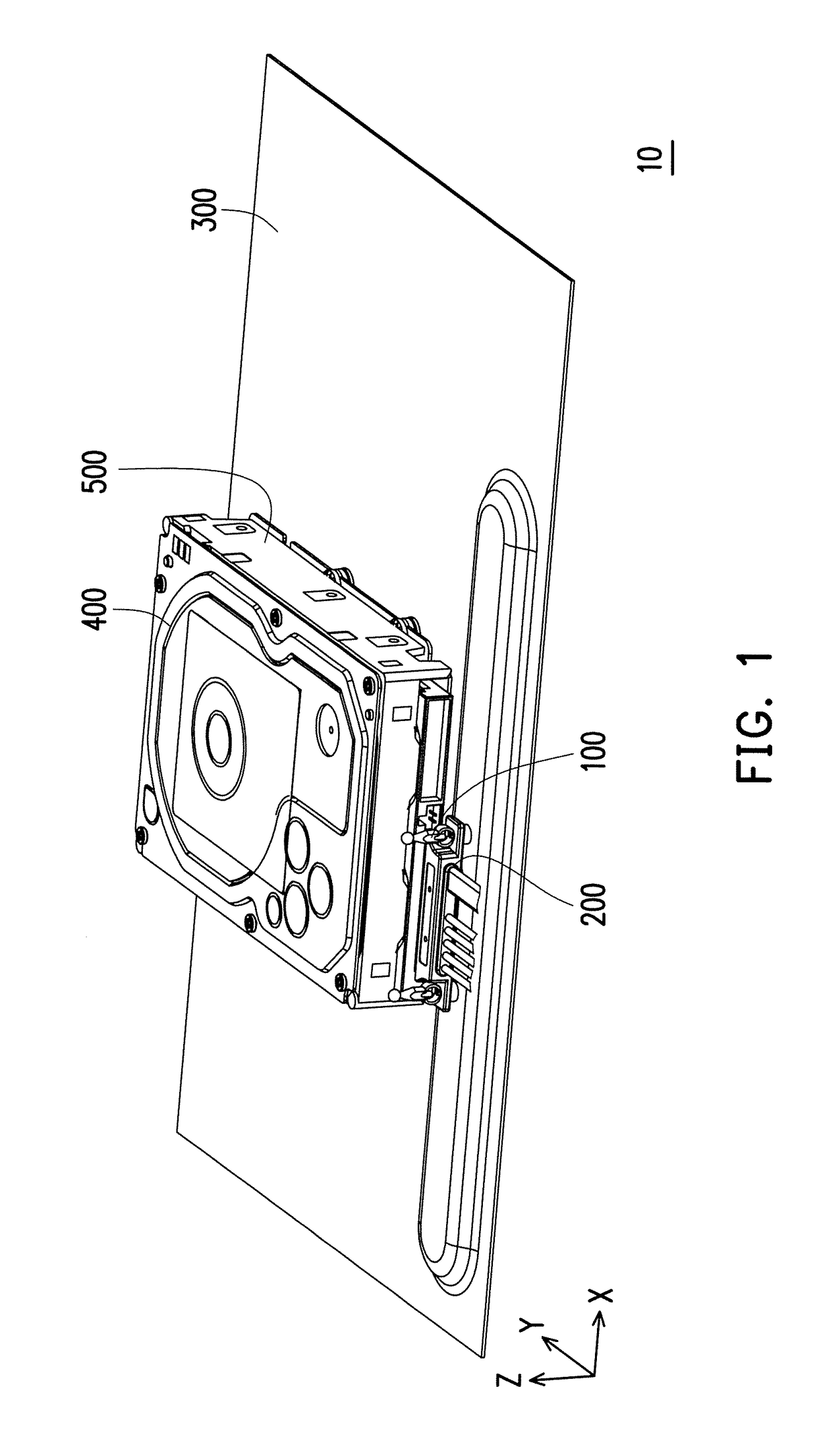
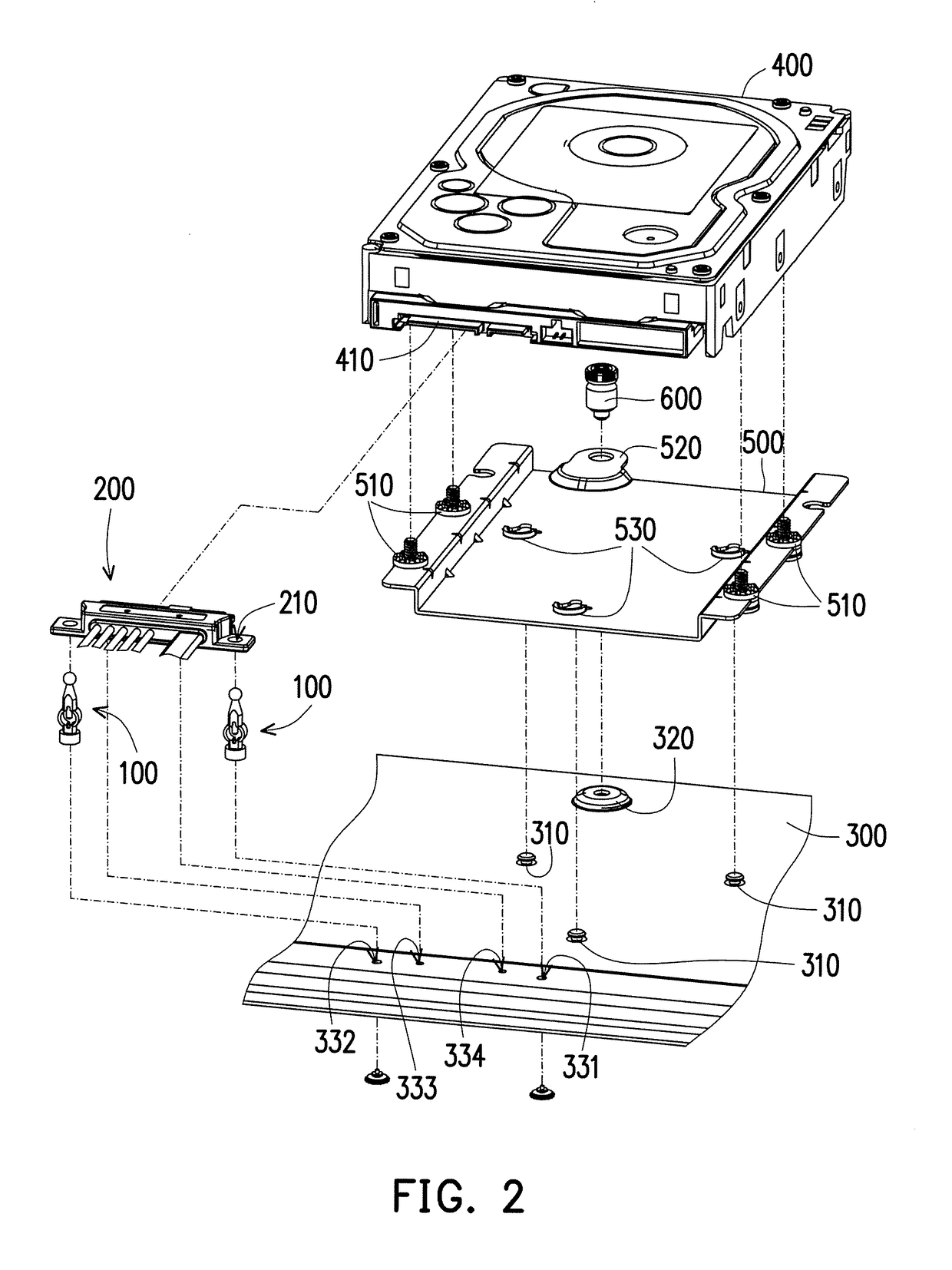
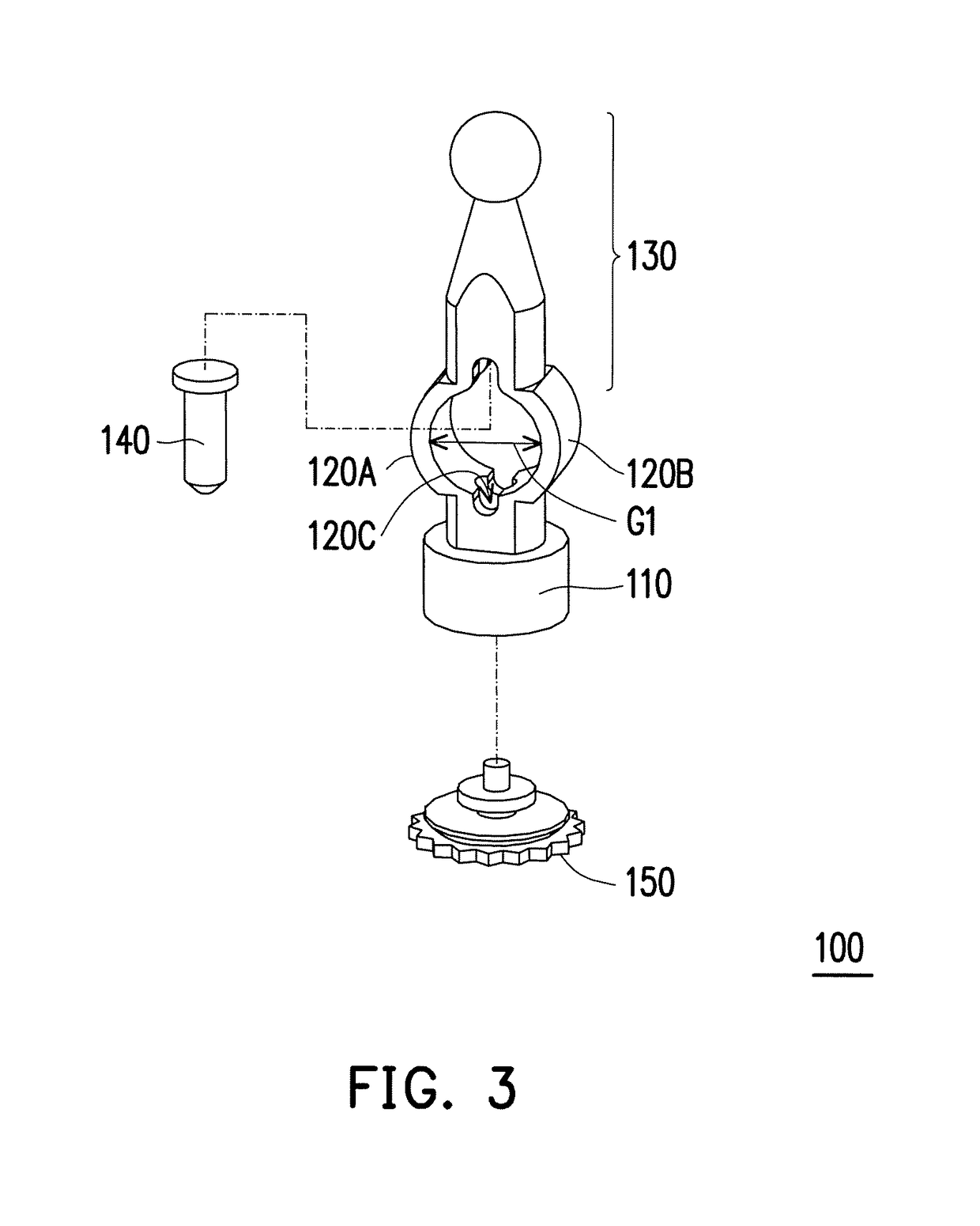
[0020]FIG. 1 is a schematic view illustrating an electronic assembly according to an embodiment of the present disclosure. FIG. 2 is an exploded view illustrating the electronic assembly of FIG. 1. Here, a Cartesian coordinate (X-Y-Z) system is provided herein for the ease of descriptions. Referring to FIGS. 1 and 2, in the embodiment, an electronic assembly 10 is a part of a structure of a server system. The electronic assembly 10 includes a carrier plate 300, a storage device 400, a bracket 500, a fastening structure 100, and a first connector 200 (e.g., a cable connector). In addition, the carrier plate 300 is adapted to be disposed in a frame of the server in a layered arrangement to be ...


PUM

PropertyMeasurementUnit
distanceaaaaaaaaaa
elastic forceaaaaaaaaaa
friction forceaaaaaaaaaa

Abstract

A fastening structure including a base pillar, a pair of elastic arms, and a top pillar is provided. The base pillar is assembled to an object, the elastic arms are connected between the top and the base pillars, and a gap is provided between the elastic arms. The top pillar is adapted to stretch or compress the elastic arms when an external force is exerted to reduce or expand the gap. The top pillar and the elastic arms pass through a through hole of a connector when the elastic arms are stretched to reduce the gap to make the connector contact the base pillar. After the force is removed, the gap between the elastic arms is restored to fasten the fastening structure between the elastic arms and the base pillar in a floating state. An electronic assembly and an operating method of the fastening structure are also provided.

Description

CROSS-REFERENCE TO RELATED APPLICATION[0001]This application claims the priority benefit of Taiwan application serial no. 106104954, filed on Feb. 15, 2017. The entirety of the above-mentioned patent application is hereby incorporated by reference herein and made a part of this specification.BACKGROUND OF THE INVENTION1. Field of the Invention[0002]The present disclosure relates to a fastening structure, an electronic assembly, and an operating method of the fastening structure.2. Description of Related Art[0003]In the conventional info nation devices, such as severs, industrial computers, disk array storage devices, external disk drive cases, network attached storage (NAS) devices, and the like, an array-type disk swap module is commonly adopted as the storage device. Normally, a disk and other components are fixed in a case by screw-locking. Namely, screws are respectively aligned to and screwed into screw holes. Such process may take a certain amount of time, and the time require...

Claims


Application Information

Patent Timeline
Patent Type & Authority Patents(United States)
IPC IPC(8): H01R13/64H05K7/14G06F1/18G11B33/00
CPCH05K7/1474G06F1/183H05K7/1417G11B33/00H05K7/1408G06F1/187F16B2/22G11B33/08G11B33/122G11B33/124
Inventor LEE, TUNG-PINGKUO, YU-LING
Owner WISTRON CORP
Learn More