
IV drip chamber with filter and bottom reservoir

a drip chamber and filter technology, applied in the field of tubing sets, can solve the problems of general failure of the typical procedure for removing air bubbles b>40/b>

Active Publication Date: 2015-03-10
BECTON DICKINSON & CO
View PDF41 Cites 9 Cited by
  • Summary
  • Abstract
  • Description
  • Claims
  • Application Information

AI Technical Summary

Benefits of technology

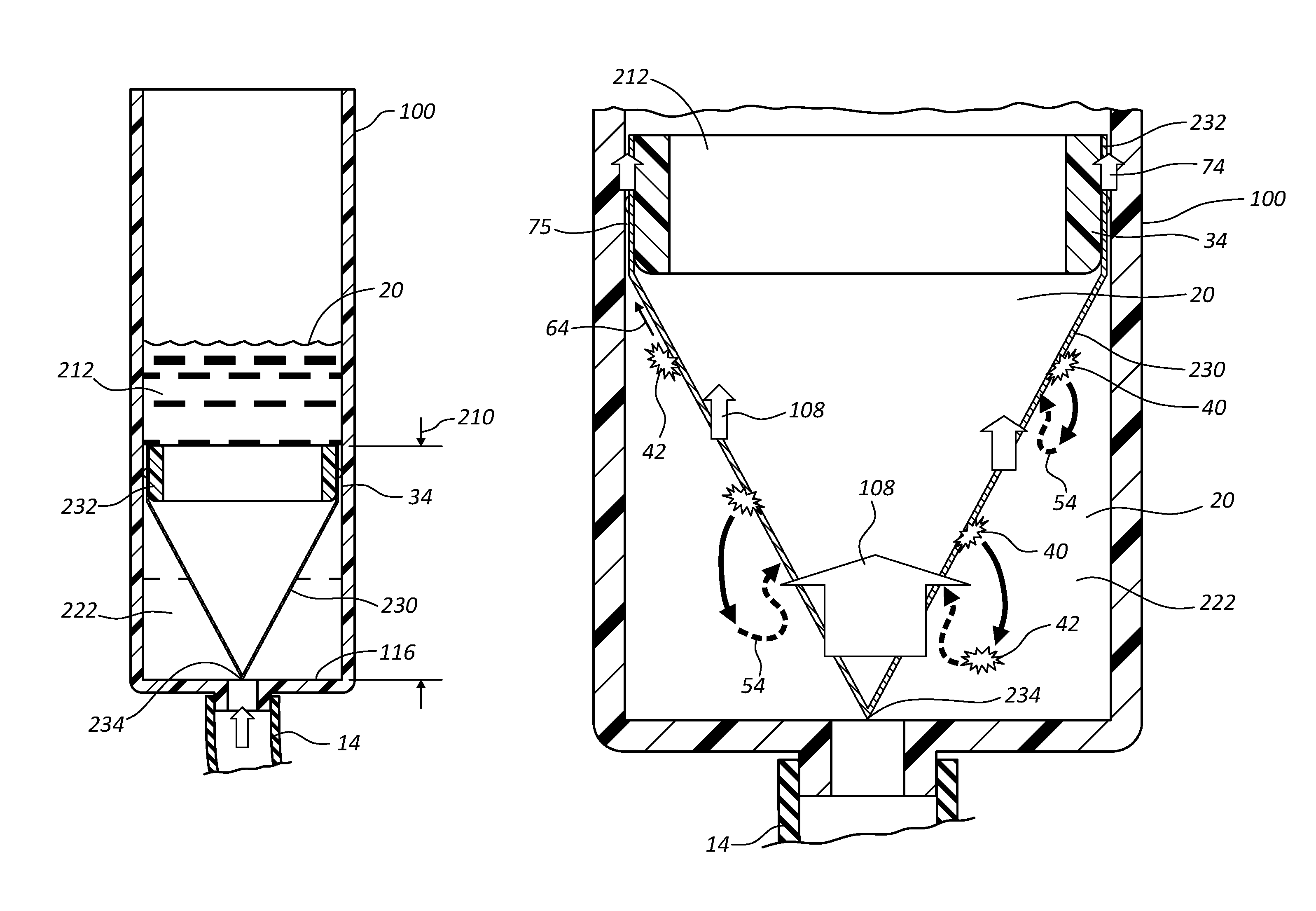
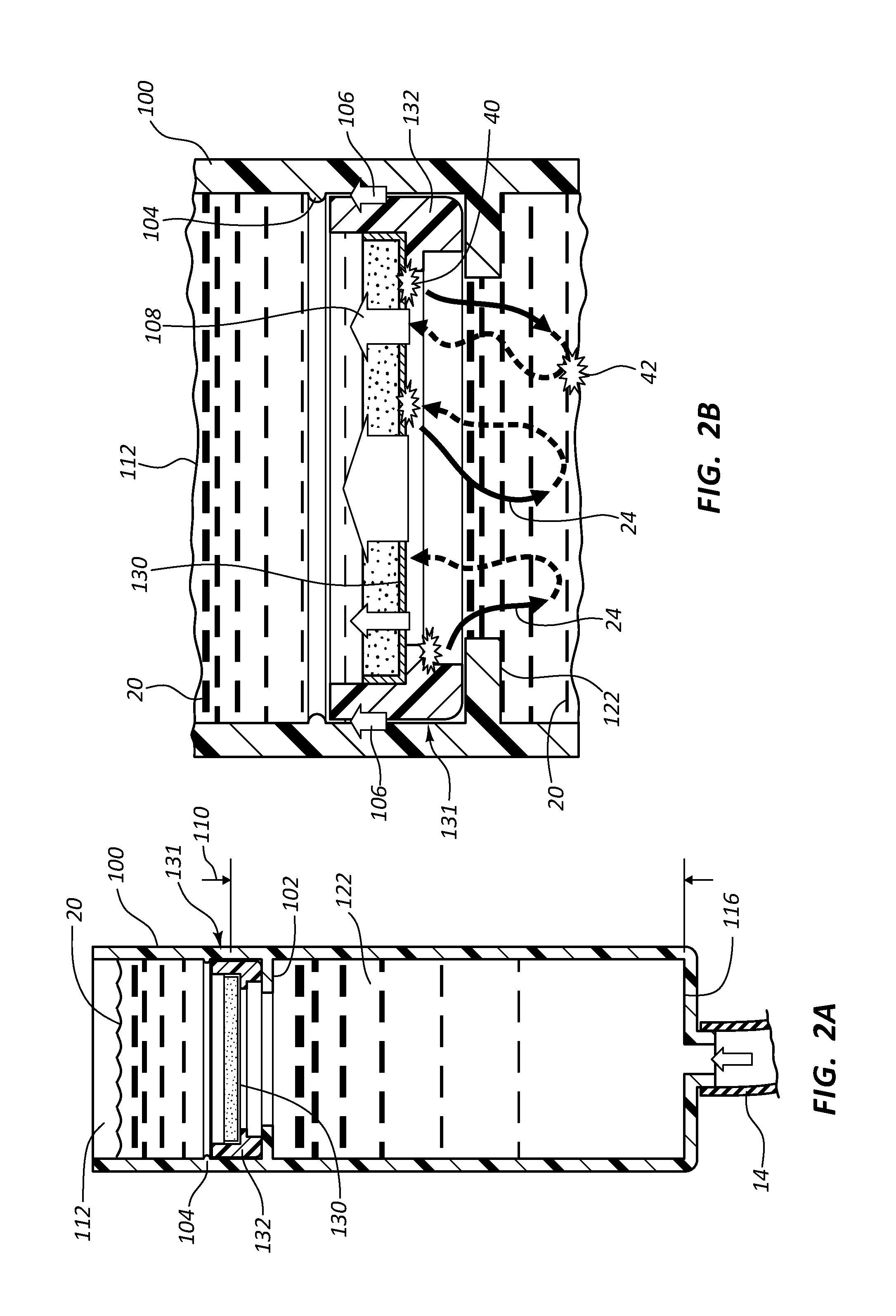
[0015]The distance between the filter assembly and the bottom surface is selected to prevent dislodged air bubbles from being drawn into the intravenous fluid line during an infusion procedure. Generally, this distance is selected by determining the height above the bottom surface at which the suction force of fluid leaving the bottom reservoir via the intravenous fluid line is less than the buoyancy of the air bubbles that become dislodged from the air filter. The placement of the filter assembly may therefore result in the upper reservoir having a volume that is less than the volume of the lower reservoir. The placement of the filter assembly may alternatively result in the upper reservoir having a volume that is greater than a volume of the lower reservoir. Further, the placement of the filter assembly may results in the upper reservoir having a volume that is approximately equal to a volume of the lower reservoir.
[0017]Some implementations of the present invention further include a method for preventing a dislodged air bubble from being drawn into an intravenous fluid line of an intravenous infusion assembly during an infusion procedure. This method includes a step for providing a drip chamber having an upper reservoir separated from a lower reservoir via a filter assembly. The drip chamber further includes a bottom surface configured to receive an intravenous fluid line. The method further includes positioning the filter assembly at a distance from the bottom surface, wherein the distance is configured to prevent an air bubble dislodged from the filter assembly from being drawn into the intravenous fluid line during an infusion procedure.

Problems solved by technology

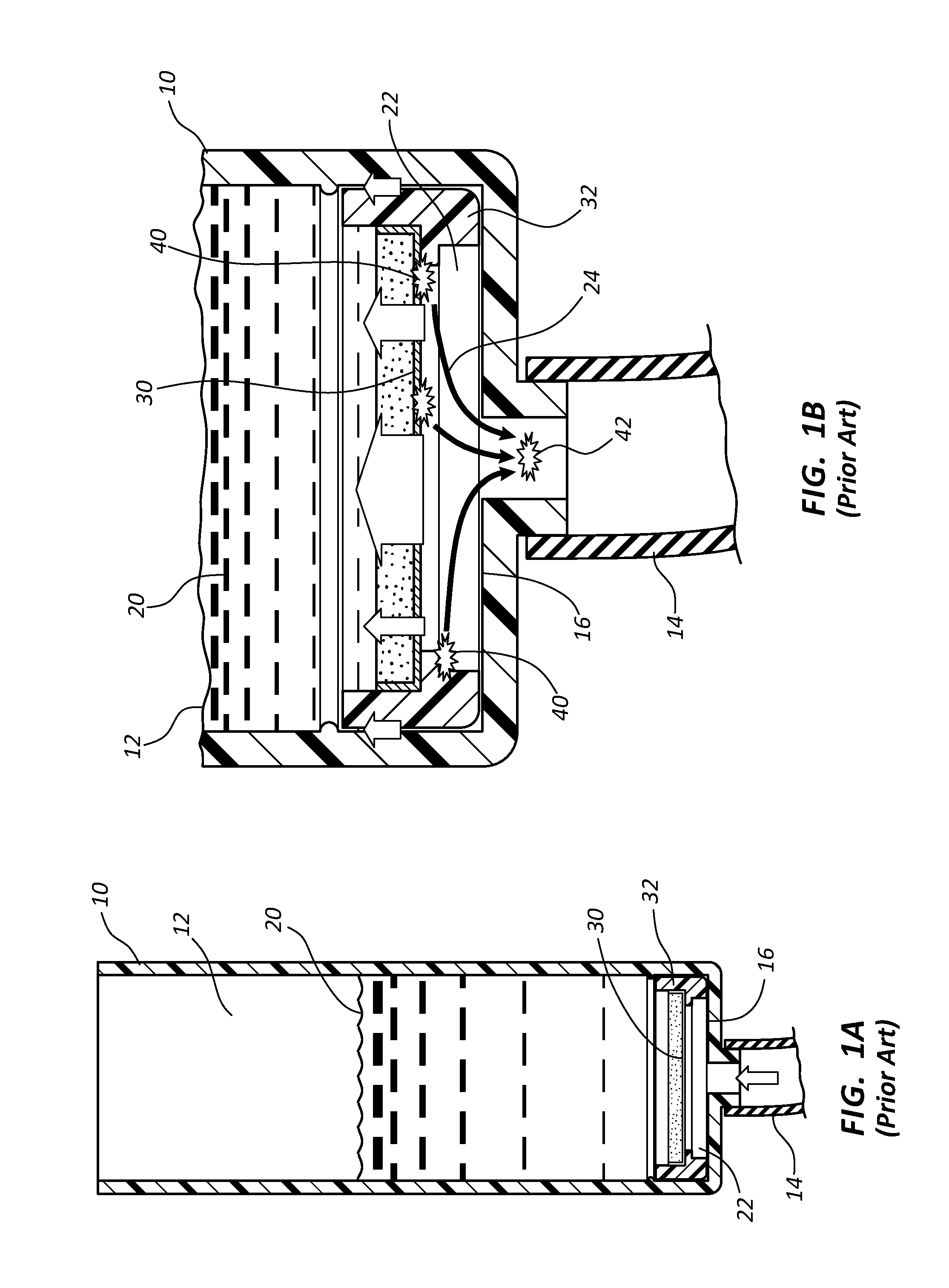
Typical procedures for removing air bubbles 40 are generally unsuccessful, such as agitating or twirling drip chamber 10.
This provides an undesirable result.

Method used


Image

  • IV drip chamber with filter and bottom reservoir
  • IV drip chamber with filter and bottom reservoir
  • IV drip chamber with filter and bottom reservoir

Examples


Embodiment Construction

[0026]The presently preferred embodiments of the present invention will be best understood by reference to the drawings, wherein like parts are designated by like numerals throughout. It will be readily understood that the components of the present invention, as generally described and illustrated in the figures herein, could be arranged and designed in a wide variety of different configurations. Thus, the following more detailed description of the embodiments of the IV drip chamber with filter and bottom reservoir of the present invention, as represented in FIGS. 1A through 4B, is not intended to limit the scope of the invention, as claimed, but is merely representative of presently preferred embodiments of the invention.

[0027]For this application, the phrases “connected to,”“coupled to,” and “in communication with” refer to any form of interaction between two or more entities, including mechanical, electrical, magnetic, electromagnetic, and thermal interaction. The phrase “attache...


PUM


Abstract

A drip chamber having an upper reservoir that is separated from a lower reservoir via a filter assembly, wherein a distance between the filter assembly and a bottom surface of the drip chamber is selected to prevent dislodged air bubbles of the filter assembly from being drawn into an intravenous fluid line that is coupled to the bottom surface of the drip chamber, during an infusion procedure.

Description

BACKGROUND OF THE INVENTION[0001]This invention relates generally to tubing sets used in the administration of liquids to a patient that are commonly referred to as intravenous (“IV”) sets and more particularly concerns bubble free, self-priming IV sets. An IV set according to the invention is used broadly herein to describe tubing sets used in the arterial, intravenous, intravascular, peritoneal, and non-vascular administration of fluid. Of course, one of skill in the art may use IV set to administer fluids to other locations than those listed within a patient's body.[0002]One common method of administering fluids into a patient's blood flow is through an IV set. An IV set is an apparatus that generally includes a connector for connection to a fluid reservoir or IV bag, a drip chamber used to determine the flow rate of fluid from the fluid reservoir, an intravenous fluid line for providing a connection between the fluid reservoir and the patient, and a catheter that may be position...

Claims


Application Information

Patent Timeline
Patent Type & Authority Patents(United States)
IPC IPC(8): A61M1/00A61M5/14A61M5/38
CPCA61M5/38A61M5/1411
Inventor ALISANTOSO, DARIUSCHENG, KIAT JINNEO, KEVIN
Owner BECTON DICKINSON & CO
Learn More