
Surgical retractor system

a retractor and surgical technology, applied in the field of surgical retractor systems, can solve the problems of reducing recovery time, reducing blood loss, and reducing the size of the current retractor, and reducing the amount of retraction

Active Publication Date: 2015-03-31
GLOBUS MEDICAL INC
View PDF5 Cites 76 Cited by
  • Summary
  • Abstract
  • Description
  • Claims
  • Application Information

AI Technical Summary

Benefits of technology

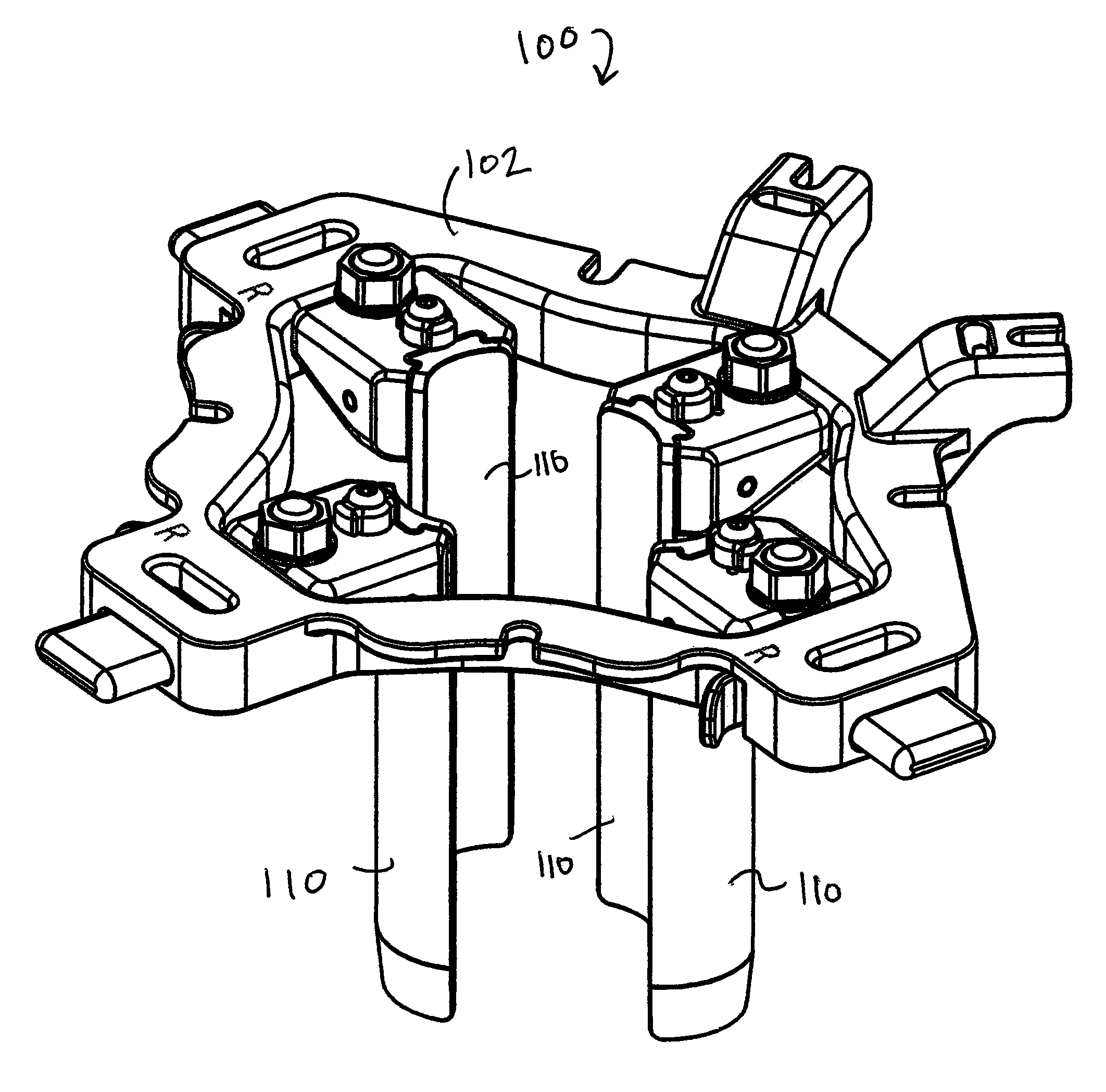
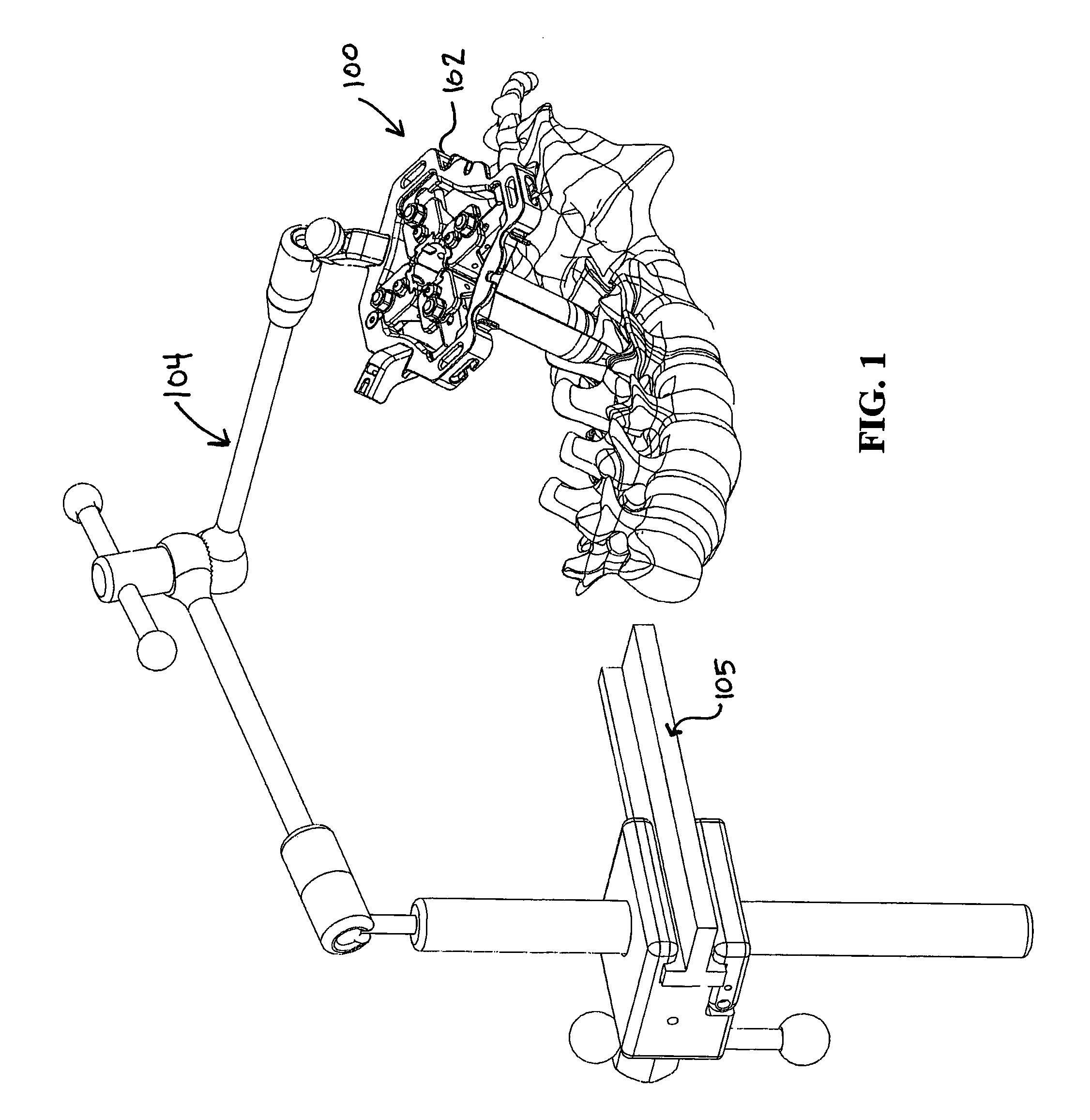
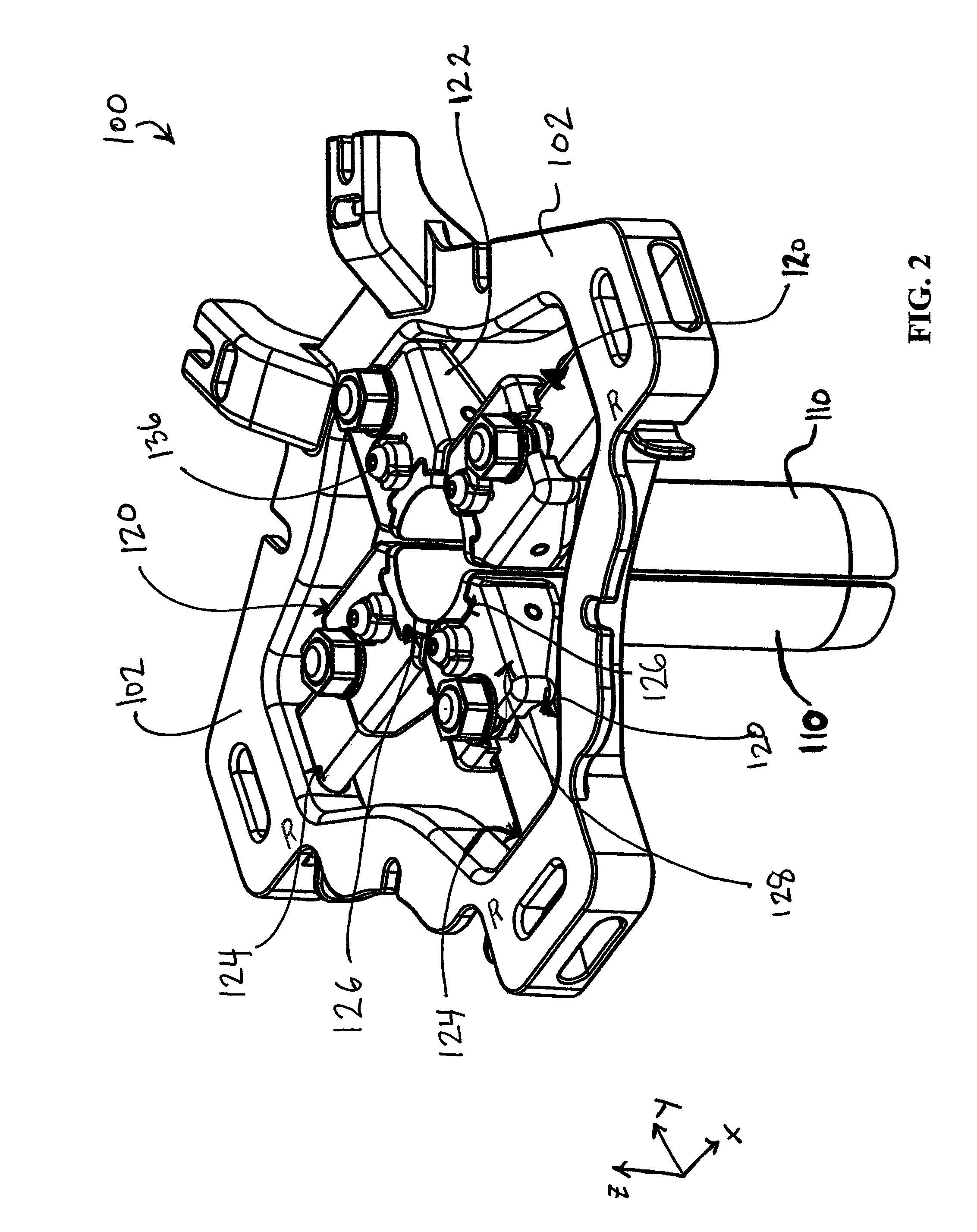
The invention is a surgical retractor system that includes a frame and multiple arms connected to the frame. The arms can move relative to the frame and are constrained to move in a specific direction. Each arm can also have a removable retractor blade that can rotate about its own axis. The system can have a frame with a polygonal shape and the moveable arms can slide with respect to the frame. The retractor blades are protected by a flexible sleeve made of materials like polyurethane rubber. The technical effects of the invention include improved retraction and protection of the surgical field.

Problems solved by technology

As a result, some physicians feel that using a minimally invasive spine surgery system generally causes less soft tissue damage, reduces blood loss and reduces recovery time.
For example, most currently available retractors are large and cumbersome, requiring a long incision length that traumatizes the patient's muscles and tissue.
Also, some current retractors provide so much variability and adjustability that they are unwieldy, fiddly, and / or difficult to adjust or maneuver and are simply impractical for use in a typical surgical environment.
However, other retractors may not provide sufficient adjustability.
For example, some retractors do not allow independent pivoting of an individual retractor blade, while others may only provide for retraction of coupled pairs of blades as opposed to independent retraction, and still others may only allow for finite adjustment constrained to a rack and pinion system or a predefined arc for pivoting.

Method used


Image

  • Surgical retractor system
  • Surgical retractor system
  • Surgical retractor system

Examples


Embodiment Construction

[0031]Embodiments of the invention will now be described. The following detailed description of the invention is not intended to be illustrative of all embodiments. In describing embodiments of the present invention, specific terminology is employed for the sake of clarity. However, the invention is not intended to be limited to the specific terminology so selected. It is to be understood that each specific element includes all technical equivalents that operate in a similar manner to accomplish a similar purpose.

[0032]The terms “first position,”“second position,” and “third position,” as used herein, merely refer to dissimilar positions and are not meant to imply that all embodiments can only be adjusted to one, two, or three positions. In some embodiments, a retractor system may be adjustable to a finite number of positions. In other embodiments, the distance between one or more components can be increased or decreased to any desired extent, thereby allowing a retractor system to ...


PUM


Abstract

A surgical retractor system having a frame and a plurality of arms connected thereto is disclosed. At least one arm is moveable relative to the frame and the relative movement is constrained to a direction along the longitudinal axis of the arm. At least one retractor blade is removably connected to each of the plurality of arms. The blade is fixably rotatable about an axis normal to the longitudinal axis of the arm to which it is connected.

Description

CROSS-REFERENCE TO RELATED APPLICATIONS[0001]This application is a continuation of U.S. application Ser. No. 11 / 422,511 filed on Jun. 6, 2006, now issued as U.S. Pat. No. 7,935,053, which is herein incorporated in its entirety by reference.FIELD OF THE INVENTION[0002]The invention generally relates to devices and methods that improve surgical procedures by, for example, providing a working space for the procedure and improving the surgical conditions for the practitioner of a procedure.BACKGROUND OF THE INVENTION[0003]In surgical procedures generally, surgeons try to keep incisions as small as possible to minimize or reduce trauma to the patient and damage to tissue. However, it is usually necessary that the surgeon have a clear view of the operating field. Also, an opening may need to be enlarged to accommodate the passing of medical implants therethrough.[0004]In the field of spine surgery, there is an increasing interest in developing minimally invasive methods, as opposed to con...

Claims


Application Information

Patent Timeline
Patent Type & Authority Patents(United States)
IPC IPC(8): A61B1/32A61B17/02
CPCA61B17/0293A61B17/0206A61B1/00135A61B1/32A61B17/0218A61B17/025A61B2017/00473A61B2017/0256
Inventor KARPOWICZ, EDWARDIOTT, ANDREW
Owner GLOBUS MEDICAL INC
Learn More