
Displaying extracted structures from an OCT image superimposed on an eyeground image

a technology of eyeground image and extraction structure, applied in image enhancement, medical science, diagnostics, etc., can solve the problems of inability to indicate the extraction reliability to a user, and the structure obtained from an eyeground image (or an slo image) is generally different from each other in extraction accuracy

Inactive Publication Date: 2015-03-31
CANON KK
View PDF8 Cites 12 Cited by
  • Summary
  • Abstract
  • Description
  • Claims
  • Application Information

AI Technical Summary

Problems solved by technology

However, a structure obtained from an OCT image and a structure obtained from an eyeground image (or an SLO image) are generally different from each other in extraction accuracy.
Therefore, it is unable to indicate extraction reliability to a user by simply displaying an extracted structure.

Method used


Image

  • Displaying extracted structures from an OCT image superimposed on an eyeground image
  • Displaying extracted structures from an OCT image superimposed on an eyeground image
  • Displaying extracted structures from an OCT image superimposed on an eyeground image

Examples


example processing

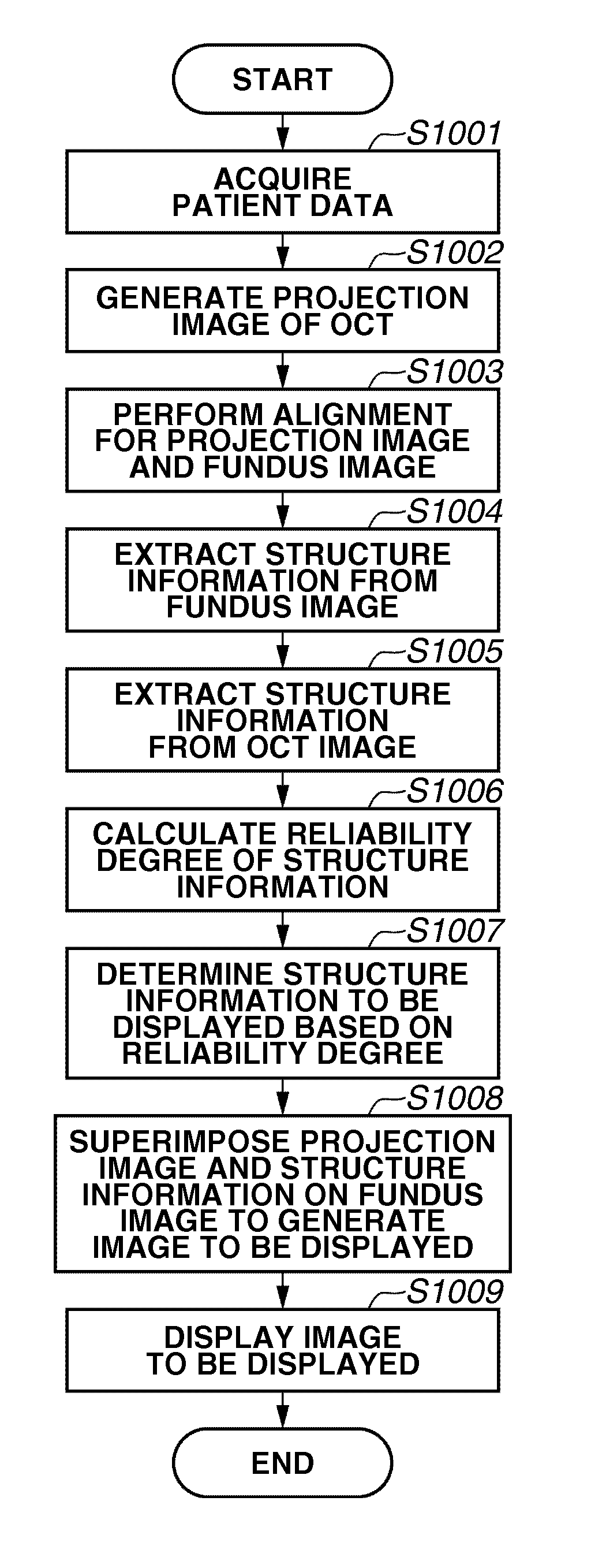
[0097 to be performed in step S807 according to the second exemplary embodiment is described in detail below with reference to FIG. 8. Processing to be executed in steps S801 to S805, S807, and S808 is similar to the processing performed in steps S401 to S407 of the flowchart illustrated in FIG. 4 described in the first exemplary embodiment and therefore the description thereof is not repeated.

[0098]In step S806, the display image generation unit 19 determines a transparency of the projection image according to an extraction result obtained by the analysis unit 15. In the present exemplary embodiment, the transparency is set to be an appropriate value in a range from 0% to 100%. When the numerical setting value is large, the transparency of a displayed image is high. In the present exemplary embodiment, if any structure information is extracted in step S804 and step S805, the display image generation unit 19 determines the transparency based on the extracted information.

[0099]FIG. 9...


PUM


Abstract

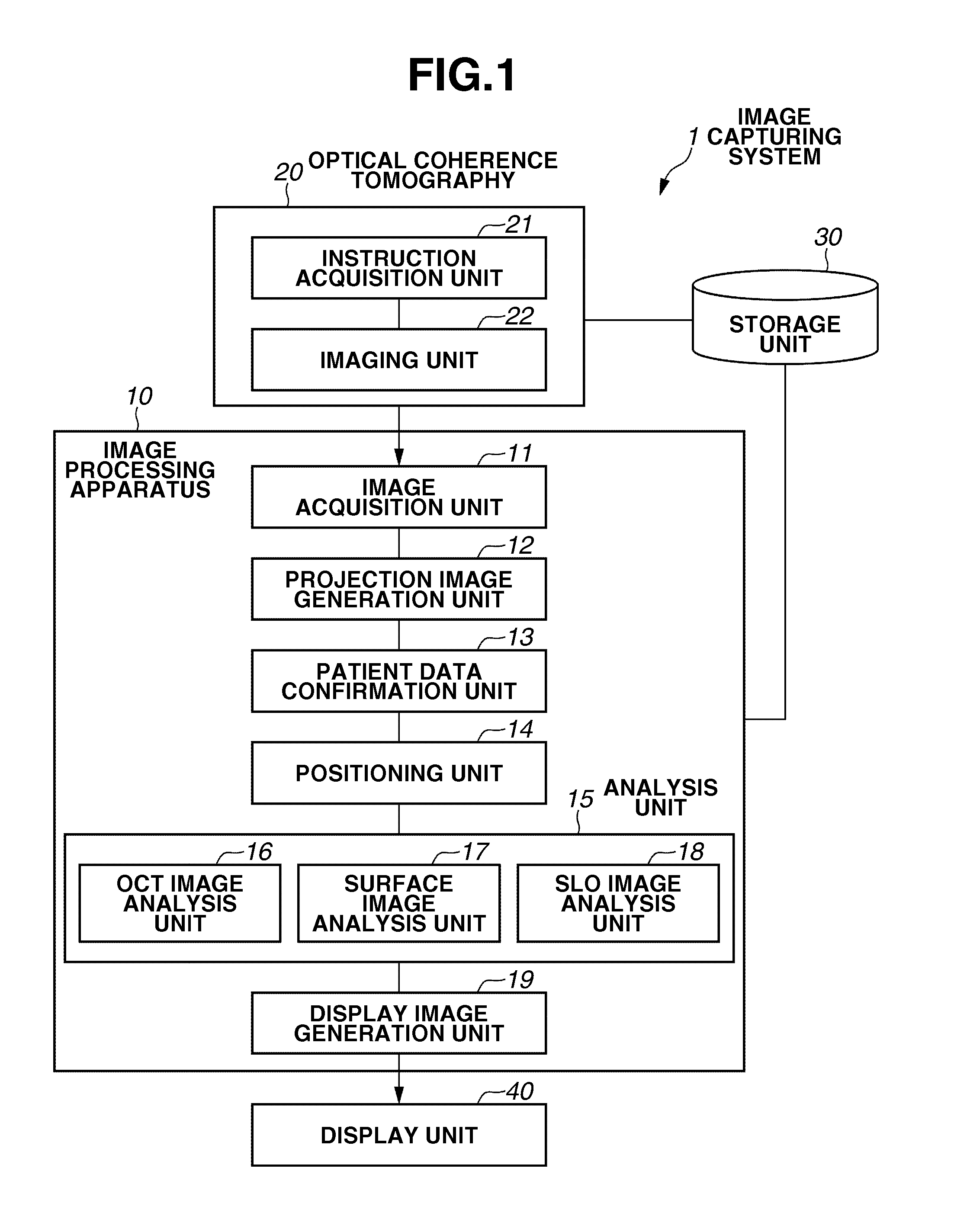
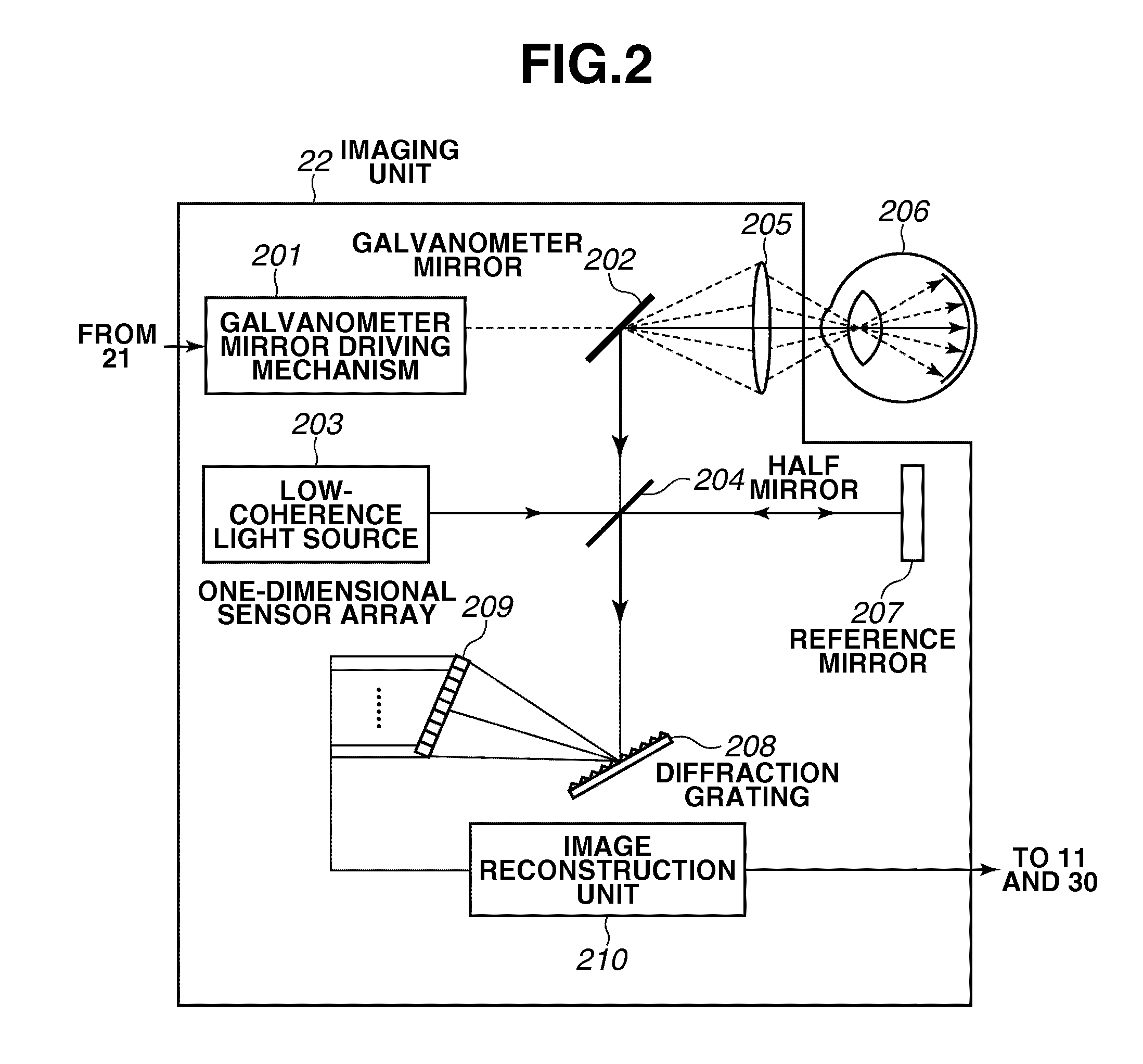
An image processing apparatus includes an extraction unit configured to extract a structure of a tested eye from an OCT image obtained by optical coherence tomography, an extraction unit configured to extract a structure of the tested eye from an eyeground image obtained by a scanning laser ophthalmoscope or a fundus camera, a calculation unit configured to calculate a reliability degree of the extraction for each of the extracted structures, and a display control unit configured to display the extracted structures superimposed on a image of eyeground according to the calculated reliability.

Description

BACKGROUND OF THE INVENTION[0001]1. Field of the Invention[0002]The present invention relates to an image processing apparatus that displays an image of a photographing target, an image processing method, an image processing system, and a computer readable program storing memory.[0003]2. Description of the Related Art[0004]In the medical field, the image diagnosis is widely performed to detect a lesioned part or check the condition of a disease based on a captured image of a tested object.[0005]The image diagnosis is employable to perform a detailed analysis based on comparison between images obtained by a plurality of different imaging apparatuses. For example, an eye doctor performs diagnosis based on an image obtained by an imaging apparatus, such as a fundus camera, a scanning laser ophthalmoscope (SLO), or an optical coherence tomography (OCT).[0006]In general, the fundus camera can obtain a color image of an eyeground surface. The scanning laser ophthalmoscope can obtain a hig...

Claims


Application Information

Patent Timeline
Patent Type & Authority Patents(United States)
IPC IPC(8): G09G5/00A61B3/00G06T5/50
CPCA61B3/0025G06T5/50G06T2207/30041G06T2207/10101G06T2207/20221
Inventor NAKANO, YUTATAKAMA, YASUFUMIMORITA, KENJI
Owner CANON KK
Learn More