Liquid crystal display apparatus

a technology of liquid crystal display and display means, which is applied in the direction of display means, illuminated signs, instruments, etc., can solve the problems of reducing detection accuracy and video image quality

Active Publication Date: 2015-04-07
SHARP KK
View PDF28 Cites 3 Cited by
  • Summary
  • Abstract
  • Description
  • Claims
  • Application Information

AI Technical Summary

Benefits of technology

[0008]The present invention aims to provide a liquid crystal display apparatus which enables to execute adjustment of white balance based on a measurement result of light emission luminance of a backlight accurately and effectively.
[0010]Another object of the present inventions is to provide the liquid crystal display apparatus, wherein the backlight is comprised of LEDs in three colors of RGB, a storage portion is provided for storing, when light of each of the LEDs of RGB is emitted in a state where white balance is adjusted in advance, light emission luminance of each of RGB detected by the backlight luminance detection portion, the backlight luminance detection portion detects light emission luminance of each of the LEDs of RGB when adjusting light emission luminance of the backlight, and the control portion compares the light emission luminance of RGB detected by the backlight luminance detection portion with light emission luminance of RGB stored in the storage portion, and adjusts, when an error occurs between the compared light emission luminance, the light emission luminance of each of the LEDs of RGB so as to eliminate the error.

Problems solved by technology

However, there is a problem that light emission luminance of a backlight of a liquid crystal apparatus is changed due to switching between light modulation levels of the backlight or an elapsed time after powered on, so that white balance varies to cause reduction in video image quality.
At this time, a transmitted light amount of the liquid crystal display panel is changed depending on a state of an optical shutter so that an amount of light incident on a detection sensor for detecting light emission luminance of the backlight does not become stable, thus resulting in reduction in detection accuracy.

Method used


Image

  • Liquid crystal display apparatus
  • Liquid crystal display apparatus
  • Liquid crystal display apparatus

Examples


Embodiment Construction

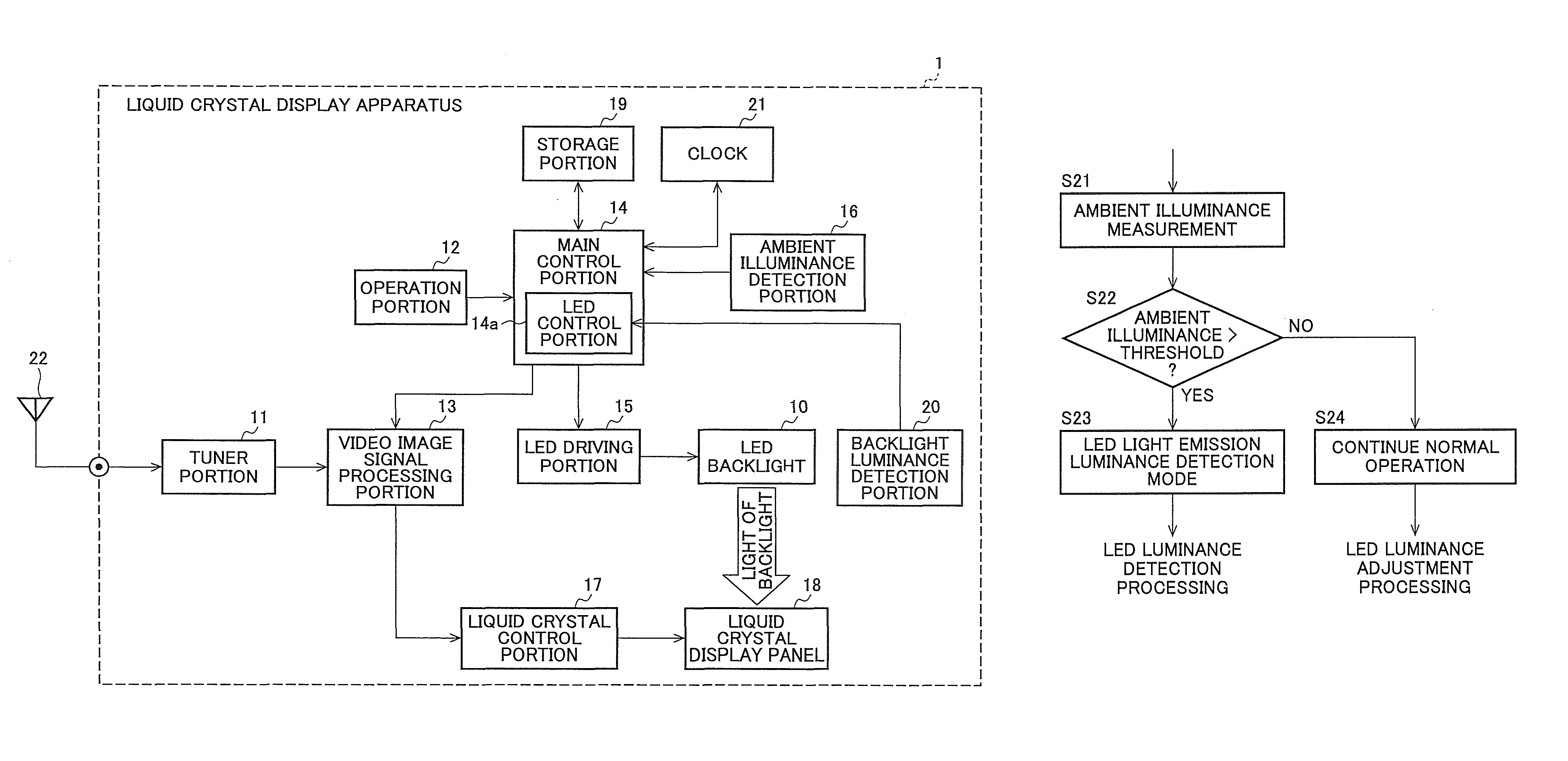
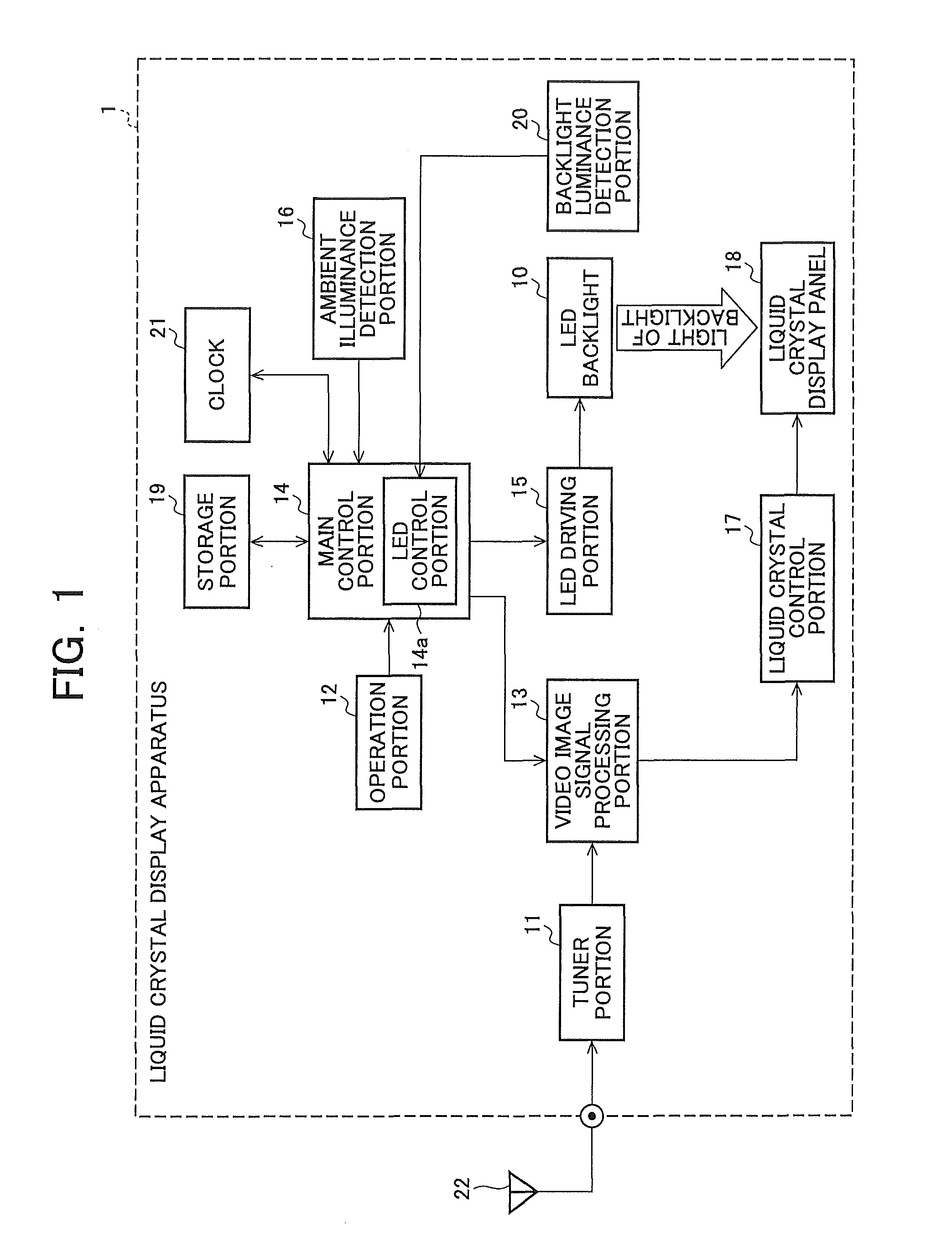
[0018]FIG. 1 is a block diagram showing a schematic configuration example of a liquid crystal display apparatus according to the present invention. A liquid crystal display apparatus 1 is provided with an LED backlight 10, a tuner portion 11, an operation portion 12, a video image signal processing portion 13, a main control portion 14, an LED driving portion 15, an ambient illuminance detection portion 16, a liquid crystal control portion 17, a liquid crystal display panel 18, a storage portion 19, a backlight luminance detection portion 20, and a clock 21.

[0019]The liquid crystal display panel 18 is a non-self luminous type panel. The LED backlight 10 which constitutes a backlight of the present invention has an LED as a light source and illuminates the liquid crystal display panel 18 from a back side thereof with light emission of the LED. The main control portion 14 controls whole inside the liquid crystal display apparatus 1 including the video image signal processing portion 1...


PUM


Abstract

Adjustment of white balance based on a measurement result of light emission luminance of a backlight is allowed to be executed accurately and effectively. A backlight luminance detection portion detects light emission luminance of an LED backlight in a state where an optical shutter of a liquid crystal display panel is closed. A main control portion adjusts light emission luminance of the LED backlight according to light emission luminance detected by the backlight luminance detection portion. Here, the main control portion compares light emission luminance of LEDs of RGB detected by the backlight luminance detection portion with light emission luminance of RGB in white balance adjustment that is stored in advance in the storage portion, and adjusts, when an error occurs between the compared light emission luminance, the light emission luminance of each of the LEDs of RGB so as to eliminate the error.

Description

CROSS-REFERENCE TO RELATED APPLICATION[0001]This non-provisional application claims a priority under 35 U.S.C. §119(a) on Patent Application No. 2011-234543 filed in JAPAN on Oct. 26, 2011, the entire contents of which are hereby incorporated herein by reference.FIELD OF THE INVENTION[0002]The present invention relates to a liquid crystal display apparatus, and more specifically, to a display apparatus provided with means to adjust white balance of a liquid crystal display panel.BACKGROUND OF THE INVENTION[0003]Recently, a monitor apparatus, a television receiver and the like using a liquid crystal display panel are becoming more and more popular. Especially, in recent years, a size of a display screen of a liquid crystal display apparatus is increased and some of which are used for a purpose of advertisement display by, for example, setting a large-screen display on a street or the like. In such a liquid crystal display apparatus, since liquid crystal itself does not emit light, a ...

Claims


Application Information

Patent Timeline
Patent Type & Authority Patents(United States)
IPC IPC(8): G09G3/36G09G3/34
CPCG09G3/3413G09G3/36G09G2320/0666G09G2360/14G09G2360/144
Inventor MASHIBA, TAMAKIYABUTA, JUNKO
Owner SHARP KK
Why Eureka
Try Eureka