

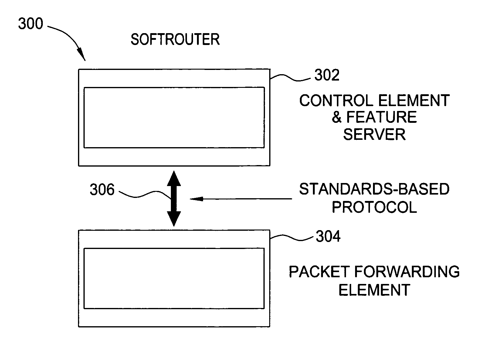
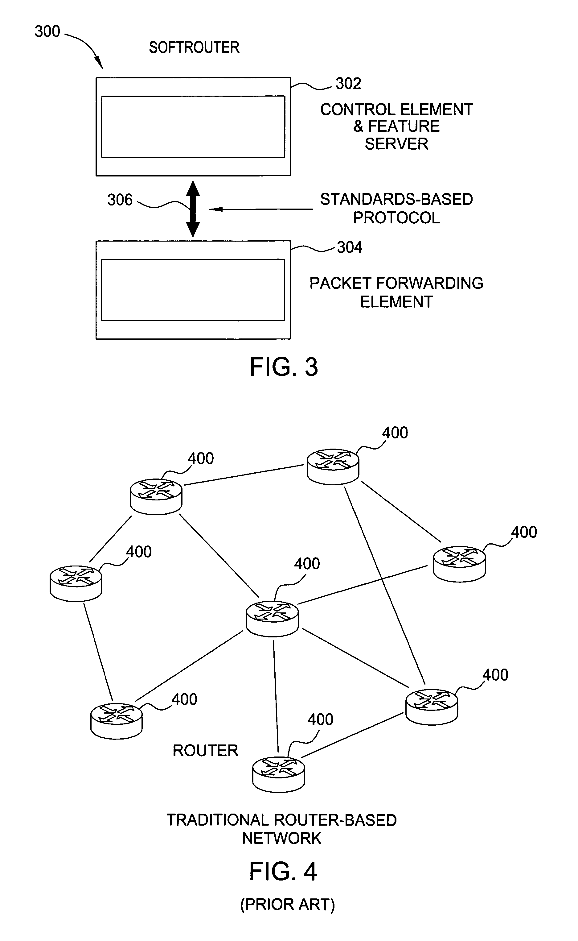
Softrouter separate control network
a technology of softrouters and control networks, applied in the field of networkwork, can solve problems such as shared failures, difficult and cumbersome to achieve in a network of autonomous and complex routers, and increasing complexity of traditional router architectures
- Summary
- Abstract
- Description
- Claims
- Application Information
AI Technical Summary
Problems solved by technology
Method used
Image

Examples
Embodiment Construction
[0018]The invention will be primarily described within the general context of an embodiment of an exemplary SoftRouter architecture, however, those skilled in the art and informed by the teachings herein will realize that the disaggregation concept may be used to generate various other embodiments of network architectures and that the invention is applicable to local area networks (LANs), metropolitan area networks (MANs), wide area networks (WANs), and other networks, such as those using open systems interconnection (OSI) layers, bridging protocols, many other protocols, traffic management, optical, edge / core routing, wireless, cable, data centers, fault management, configuration management, accounting management, performance management, security management, other network management, enterprise, government, military applications, and many other different kinds of networking characteristics and applications.
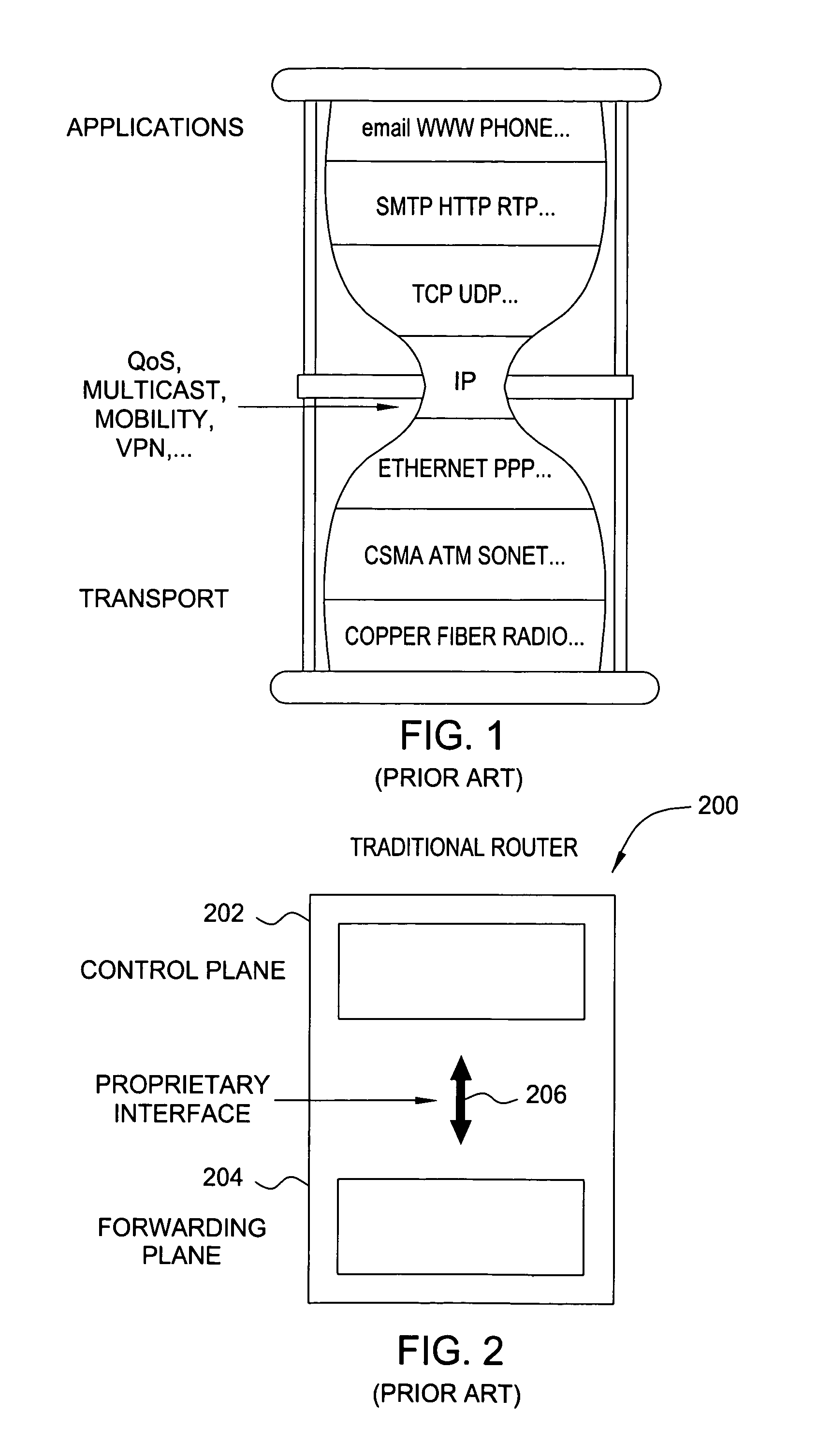
[0019]Internet protocol (IP) provides end-to-end datagram delivery service t...
PUM
 Abstract
Description
Claims
Application Information