Protective material applicator device

a technology of protective material and applicator, which is applied in the direction of transportation and packaging, other domestic objects, and casings/cabinets/drawer details, etc., can solve the problems of messy use of wet fluid solutions, high user labor, and inconvenient thickness cases, so as to reduce or eliminate air bubbles and eliminate waiting time

Active Publication Date: 2015-05-19
SUPERIOR COMM
View PDF94 Cites 21 Cited by
  • Summary
  • Abstract
  • Description
  • Claims
  • Application Information

AI Technical Summary

Benefits of technology

[0009]Devices, methods and systems are provided to apply a protective film on a surface of an electronic device which reduces or eliminates air bubbles and eliminates the waiting time usually required when using a wet fluid solution.
[0010]In one embodiment, a roller apparatus may be used in a protective film application process to eliminate air bubbles and assist the user in applying the film to the electronic device correctly. The roller apparatus may include a carriage or housing, one or more rollers coupled to or integrated with the housing and a splitter configured to separate the protective film from a backing material during the application process.
[0014]In one embodiment, a roller apparatus may include an integrated stand for propping up or holding the electronic device. In a first operational configuration, the roller apparatus may be used in a protective film application process to eliminate air bubbles and assist the user in applying the film to the electronic device correctly. In a second operational configuration, the roller apparatus may be used as a stand for propping up the electronic device. The roller apparatus may include a carriage or housing, one or more rollers coupled or integrated with the housing and a stand portion for propping up the electronic device.
[0021]In one embodiment, provided is a screen protector application system for applying a protective film to a surface of a mobile communication device, the system comprising: a body defining a cavity configured to receive the mobile communication device, the body having: a supporting surface defining an upper boundary of the cavity and being positioned outside of the cavity, and a pair of rails raised above the supporting surface and being separated from one another by at least the cavity; a protective film having an application portion and a backing portion, and a first end and a second end separated by a length of the protective film, the first end configured to couple to the body, with the length extending over the cavity; and a flange configured to couple to the protective film and being sized to fit between and abut each of the rails when the protective film is applied to the surface of the mobile communication device, to reduce movement of the application portion towards at least one of the rails when the protective film is applied to the surface of the mobile communication device.

Problems solved by technology

However, with the progress of touch-based screens for operating these electronic devices, thick cases might not be suitable, as these cases may prevent the user from operating the device.
Despite the benefits that these films or screen protectors provide, many drawbacks remain in this relatively new technology.
Using a wet fluid solution is messy, requires a lot of work by the user to “squeegee” the excess out, and might not eliminate all annoying air bubbles immediately.
Indeed, many of these products warn that 24-48 hours may be needed before the user can effectively determine if the trapped air bubbles are going to disappear.
In other words, some consumers may have to wait for days before determining if the film was applied correctly.
To some consumers, this long wait is annoying and may reduce the enthusiasm of an otherwise exciting moment of obtaining a cutting-edge electronic device.
Moreover, the electronic device might not be functional until the solution dries out in 24-48 hours.

Method used


Image

  • Protective material applicator device
  • Protective material applicator device
  • Protective material applicator device

Examples


Embodiment Construction

[0102]Apparatus, systems and / or methods that implement the embodiments of the various features of the present invention will now be described with reference to the drawings. The drawings and the associated descriptions are provided to illustrate some embodiments of the present invention and not to limit the scope of the present invention. Throughout the drawings, reference numbers are re-used to indicate correspondence between referenced elements.

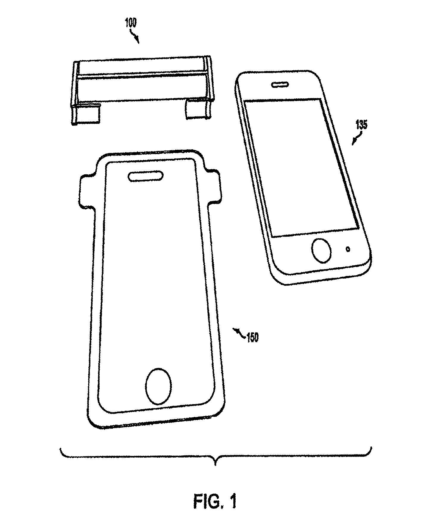
[0103]FIG. 1 illustrates a roller apparatus 100, an electronic device 135 and a film 150. The roller apparatus 100 may be used to apply the film 150 to a surface of the electronic device 135. The film 150 may protect the electronic device 135 from damage (e.g., scratches) and / or smudges. As shown, the roller apparatus 100 may have a width wider than the width of the electronic device 135 and the film 150. In this manner, the roller apparatus 100 may be configured to apply films of varying sizes onto devices of varying sizes. In addition, th...


PUM

PropertyMeasurementUnit
widthaaaaaaaaaa
lengthaaaaaaaaaa
widthaaaaaaaaaa

Abstract

Devices, methods and systems disclosed herein relate to the application of a protective film on a surface of an electronic device that instantly reduces air bubbles and eliminates the waiting time usually required when using a wet fluid solution. In one embodiment, a flange may be configured to couple to the protective film. The flange may aid in the accurate application of the protective film to the electronic device.

Description

CROSS REFERENCE TO RELATED APPLICATIONS[0001]This application is a continuation-in-part of U.S. patent application Ser. No. 13 / 361,562 entitled “PROTECTIVE MATERIAL APPLICATOR DEVICE” filed on Jan. 30, 2012, which is in turn a continuation-in part of U.S. patent application Ser. No. 13 / 208,264 entitled “PROTECTIVE MATERIAL APPLICATOR DEVICE” filed on Aug. 11, 2011, now U.S. Pat. No. 8,393,377, which in turn is a continuation-in-part of U.S. patent application Ser. No. 13 / 053,081 entitled “PROTECTIVE MATERIAL APPLICATOR DEVICE” filed on Mar. 21, 2011, now U.S. Pat. No. 8,905,107, which in turn claims the benefit of and the priority of U.S. Provisional Application No. 61 / 444,597 filed on Feb. 18, 2011. The entire contents of all of these applications are hereby incorporated by reference herein.BACKGROUND[0002]1. Field[0003]The present invention relates to an apparatus, method and / or system for applying a protective material or layer to a surface of a device. For example, the present i...

Claims


Application Information

Patent Timeline
Patent Type & Authority Patents(United States)
IPC IPC(8): B29C65/00B65C9/18B29C63/00B29C63/02B29L31/34B32B37/00B32B38/10H04M1/02H05K5/03H05K13/00H05K13/04
CPCB29C63/0004B29C63/0047B29C63/02Y10T156/1788H04M1/0283H04M1/0266B32B37/0007B32B37/0023B32B37/0053B32B38/10H05K5/03H05K13/0053H05K13/0447B29C63/0056B29L2031/3437B29C2063/0008Y10T156/137Y10T156/18B32B37/10B32B37/18B32B2457/208
Inventor PATEL, SHRADDHALACOLLA, CHARLIECHOU, VIVIAN
Owner SUPERIOR COMM
Why Eureka
Try Eureka