Electrokinetic enhanced hydrocarbon recovery from oil shale

a technology of enhanced hydrocarbon recovery and oil shale, which is applied in the direction of fluid removal, earth-moving drilling, borehole/well accessories, etc., can solve the problems of unreliable recovery results, unsatisfactory economic benefits, and long time-consuming shell approach, so as to achieve more environmental protection, more economical, and more efficient in producing commercial products

Inactive Publication Date: 2015-05-19
CHEVROU USA INC
View PDF414 Cites 21 Cited by
  • Summary
  • Abstract
  • Description
  • Claims
  • Application Information

AI Technical Summary

Benefits of technology

[0010]The present invention is directed to processes for producing mobile products from the organic matter that occurs in subsurface oil shale. Among other factors, these processes are based on the discovery that kerogen in oil shale can be made to react at temperatures below pyrolysis temperatures to produce mobile reaction products that can be removed from the subsurface shale formation, recovered in surface facilities and upgraded to produce useful products, refinery feedstocks, fuel and lubricant blendstocks, reaction intermediates and the like. The presently disclosed processes are more environmentally benign, more economical, and more efficient in producing commercial products.

Problems solved by technology

Regardless, world energy consumption continues to rise at a rate that outpaces new oil discoveries.
While the establishment of “freeze walls” is an accepted practice in civil engineering, its application to oil shale recovery still has unknown environmental impacts.
Additionally, the Shell approach is recognized as an energy intensive process and requires a long timeframe to establish production from the oil shale.

Method used


Image

  • Electrokinetic enhanced hydrocarbon recovery from oil shale
  • Electrokinetic enhanced hydrocarbon recovery from oil shale
  • Electrokinetic enhanced hydrocarbon recovery from oil shale

Examples


example 1

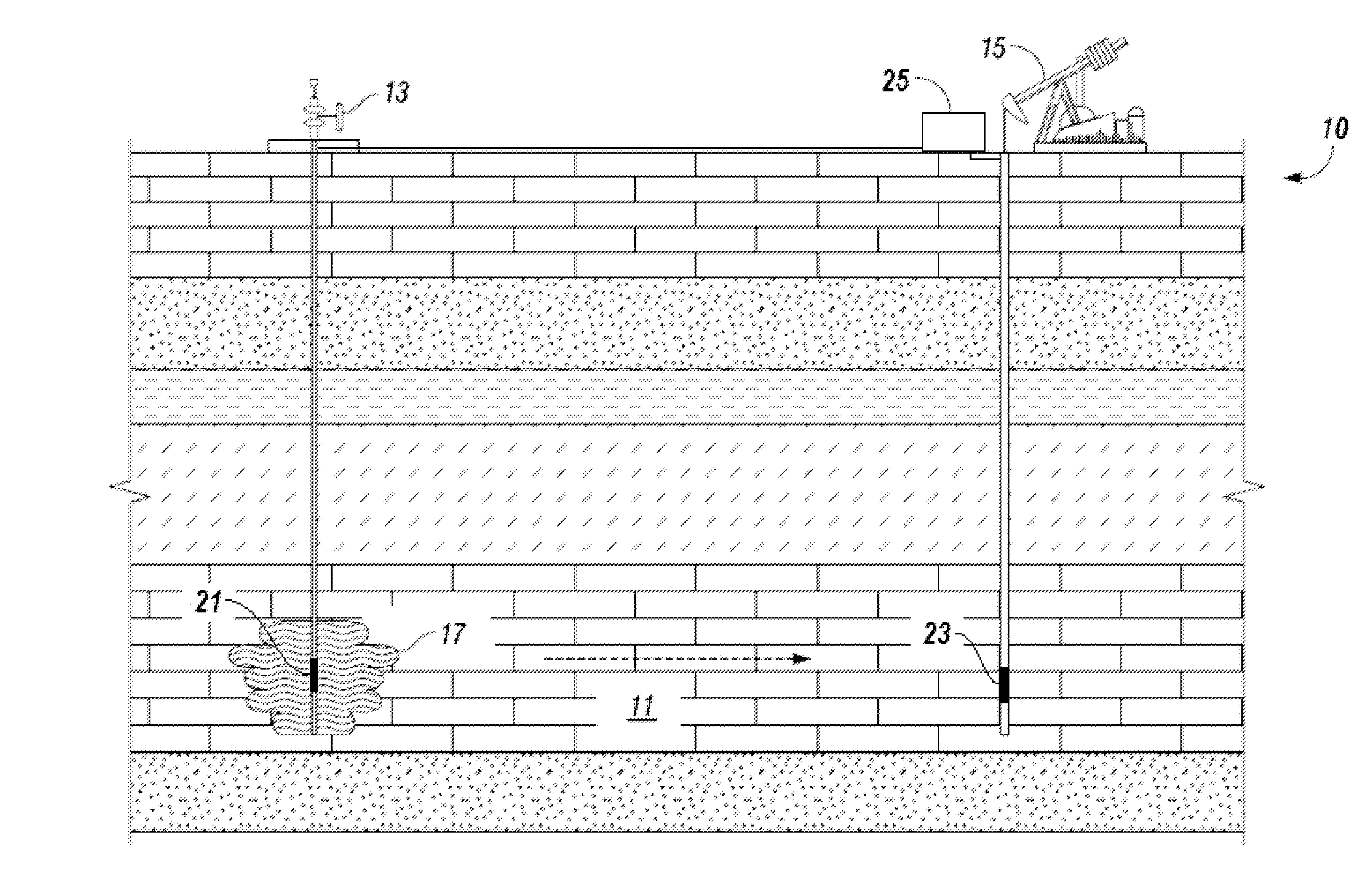
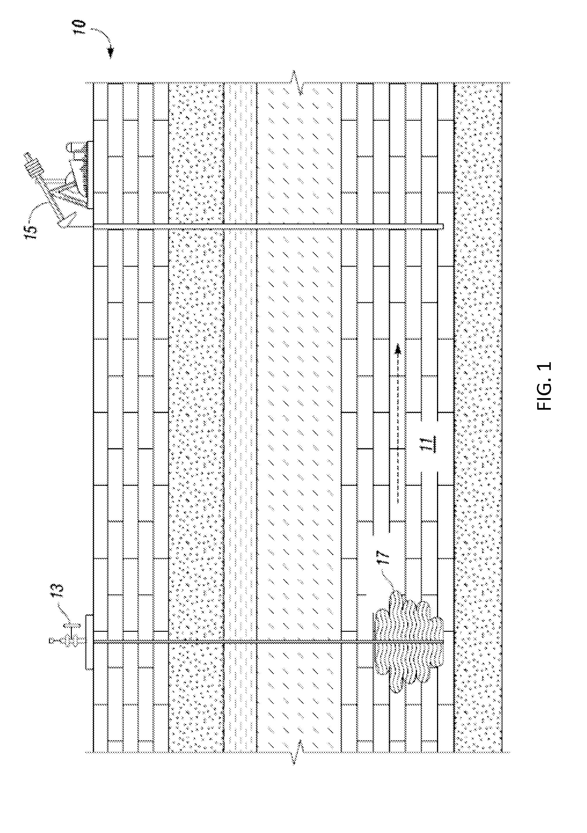
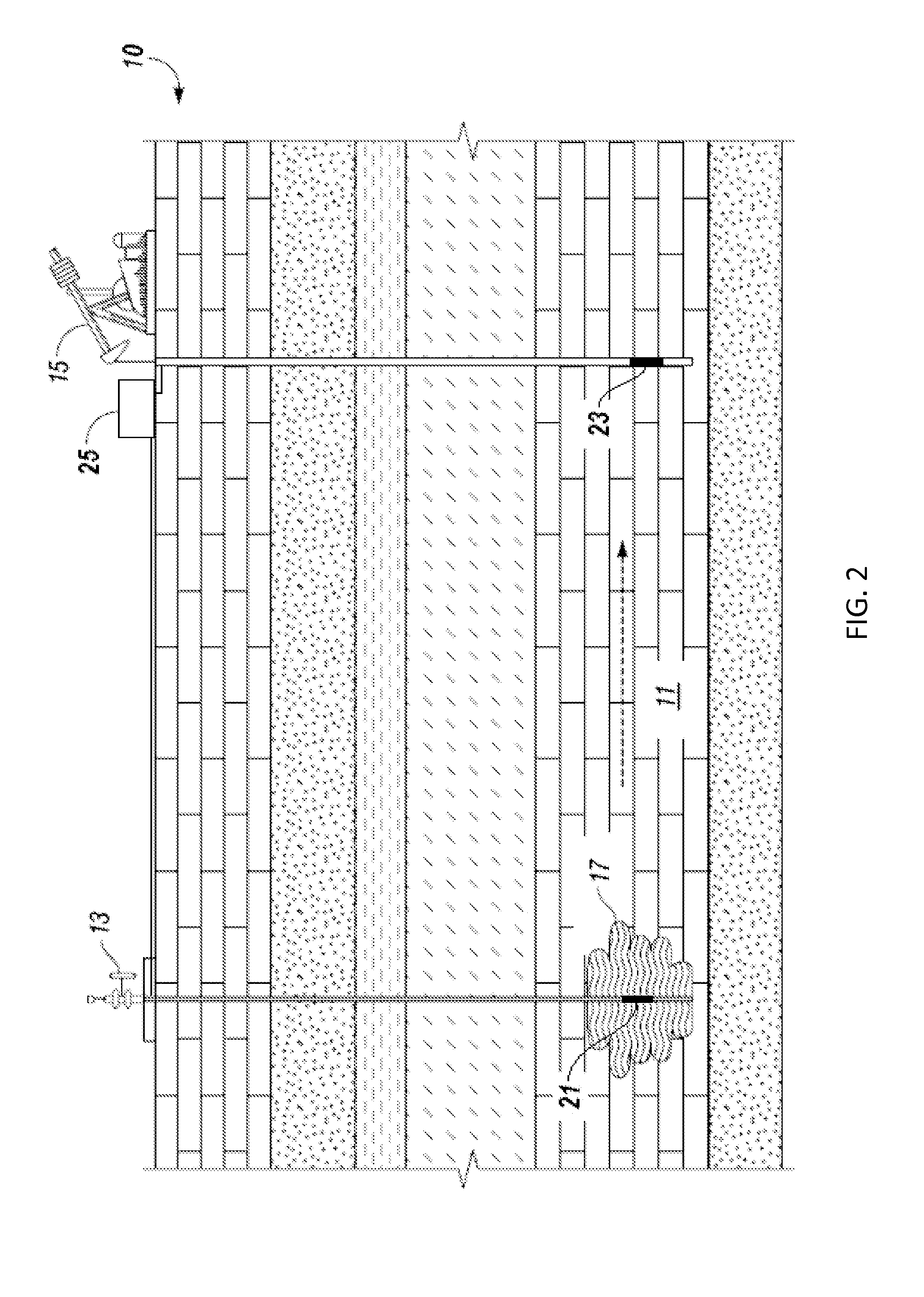
[0180]The advantages of electrokinetic-induced migration over traditional hydraulic delivery is illustrated in the following experiment. A thin glass tank having a width of about 4 cm was constructed to simulate a two-dimensional flow field through a heterogeneous porous media. House-brick sized pieces of clay, which represent low permeability features, were emplaced within a zone of contiguous glass beads. The glass beads represent the high permeability zones of channeled flow. The tank was saturated with water and a flow field was established across the apparatus by fixing the hydraulic head (water elevation) at different heights on either side of the tank. Potassium permanganate was introduced into one side of the tank and allowed to flow through the apparatus. The potassium permanganate was substantially distributed within the glass beads after two hours. However, essentially no infiltration into the clay bricks occurred, indicating that the potassium permanganate bypassed the l...

example 2

[0181]This example illustrates the effectiveness of potassium permanganate for producing high molecular weight organic acids in reactions with kerogen.

[0182]Kerogen was separated from a sample of oil shale that contained kerogen. The separated kerogen was largely organic matter, with a small amount of inorganic matter remaining from the inorganic substrate in which the kerogen originated. For this example, 2.50 grams of kerogen (organic matter basis) was combined with a solution containing 0.5 g KMnO4 in 100 ml of 1% KOH solution. The kerogen / KMnO4 mixture was stirred at 75° C. until the solution had lost its color, with no visual evidence of the purple permanganate color remaining In general, this reaction took several hours, and up to 12 hours in some cases. The kerogen was then allowed to settle, and was separated from the solution. The kerogen was then rinsed with two 75 ml aliquots of 1% KOH solution. The two rinse solutions were set aside. The rinsed kerogen was then contacted...


PUM


Abstract

Disclosed herein are methods for extracting a kerogen-based product from subsurface (oil) shale formations. These methods rely on chemically modifying the shale-bound kerogen using a chemical oxidant so as to render it mobile. The oxidant is provided to a formation fluid in contact with the kerogen in the subsurface shale utilizing electrokinetic-induced migration. An electric field is generated through at least a portion of the kerogen rich zone to induce electrokinetic migration of the oxidant. A mobile kerogen-based product, that includes reaction products of kerogen conversion, is urged toward a production well utilizing electrokinetic-induced migration, and withdrawn from the subsurface shale formation. An electric field generated through at least a portion of the kerogen rich zone can also be utilized to induce migration of catalysts or catalyst precursors.

Description

RELATED APPLICATION[0001]This application is a continuation-in-part of U.S. patent application Ser. No. 13 / 161,885, filed Jun. 16, 2011 (US Patent Publication No. US 2012-0152570), the contents of which are incorporated herein by reference in their entirety. U.S. patent application Ser. No. 13 / 161,885 claims the benefit of U.S. Provisional Application No. 61 / 425,517 filed Dec. 21,2010. The subject application is also related to U.S. Provisional Application No. 61 / 426,340, filed Dec. 22, 2010; U.S. patent application Ser. No. 13 / 335,409 (US Patent Publication No. US 2012-0160486), entitled “In-Situ Kerogen Conversion and Recovery” filed Dec. 22, 2011; U.S. patent application Ser. No. 13 / 335,525 (US Patent Publication No. US 2012-0175114), entitled “In-Situ Kerogen Conversion and Product Isolation” filed Dec. 22, 2011; U.S. patent application Ser. No. 13 / 335,607 (US Patent Publication No. US 2012-0175115), entitled “In-Situ Kerogen Conversion and Upgrading” filed Dec. 22, 2011; U.S. p...

Claims


Application Information

Patent Timeline
Patent Type & Authority Patents(United States)
IPC IPC(8): E21B43/00E21B43/16E21B43/24
CPCE21B43/16E21B43/2401
Inventor THOMAS, DAVID GLYNNWIGAND, MARCUS O.
Owner CHEVROU USA INC
Why Eureka
Try Eureka