Head-mount type display device

a display device and head-mounted technology, applied in the field of head-mounted display devices, can solve problems such as the difficulty of visually recognizing virtual images

a display device and head-mounted technology, applied in the field of head-mounted display devices, can solve problems such as the difficulty of visually recognizing virtual images

US9046686B2Active Publication Date: 2015-06-02SEIKO EPSON CORP

Image

  • Head-mount type display device
  • Head-mount type display device
  • Head-mount type display device

Examples


Embodiment Construction

[0025]Hereinafter, a preferred embodiment of the invention will be described in detail with reference to the accompanying drawings. It should be noted that the embodiment described below does not unreasonably limit the contents of the invention as set forth in the appended claims. Further, all of the constituents described below are not necessarily essential elements of the invention.

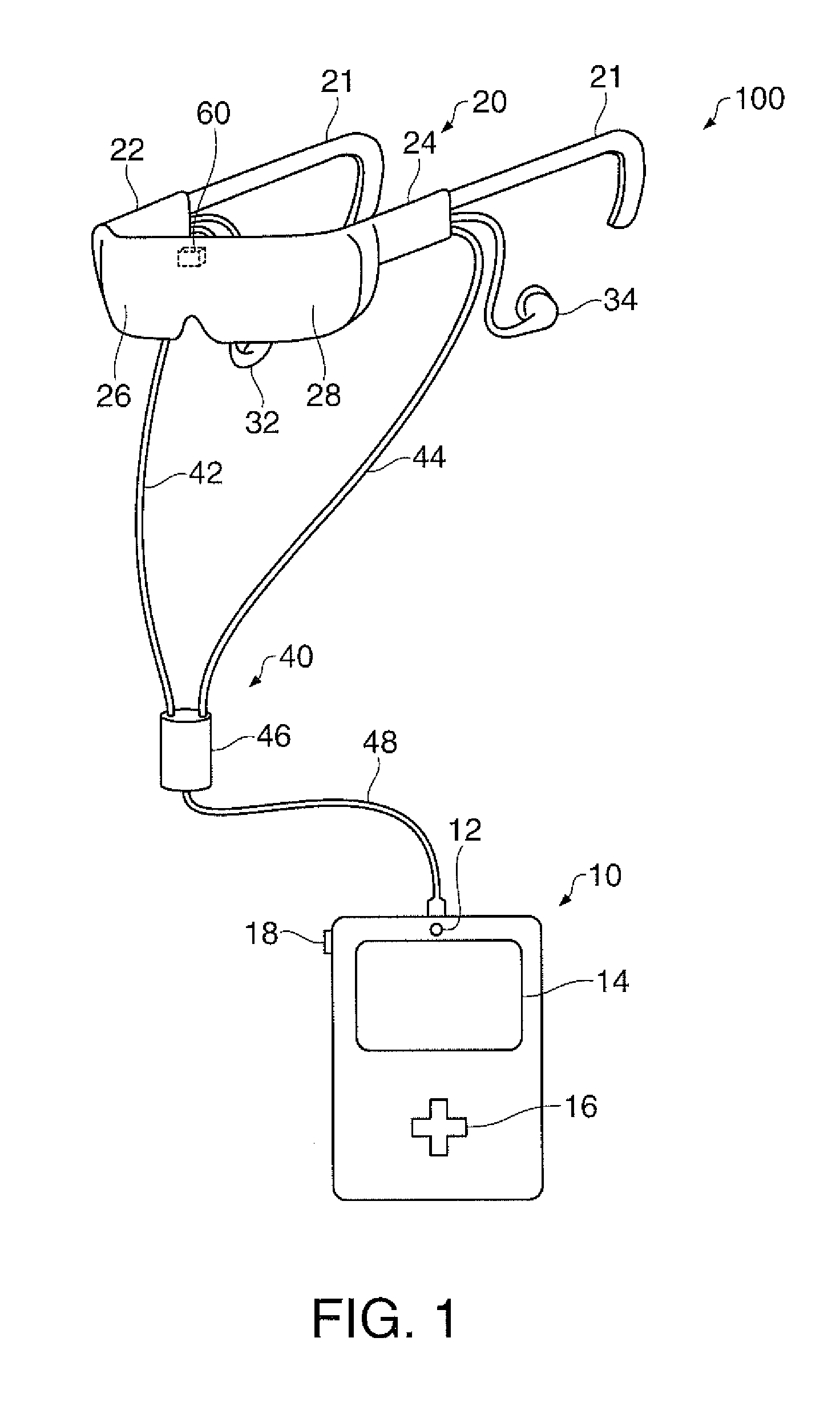
[0026]FIG. 1 is an appearance diagram showing an example of a configuration of a head-mount type display device according to the present embodiment.

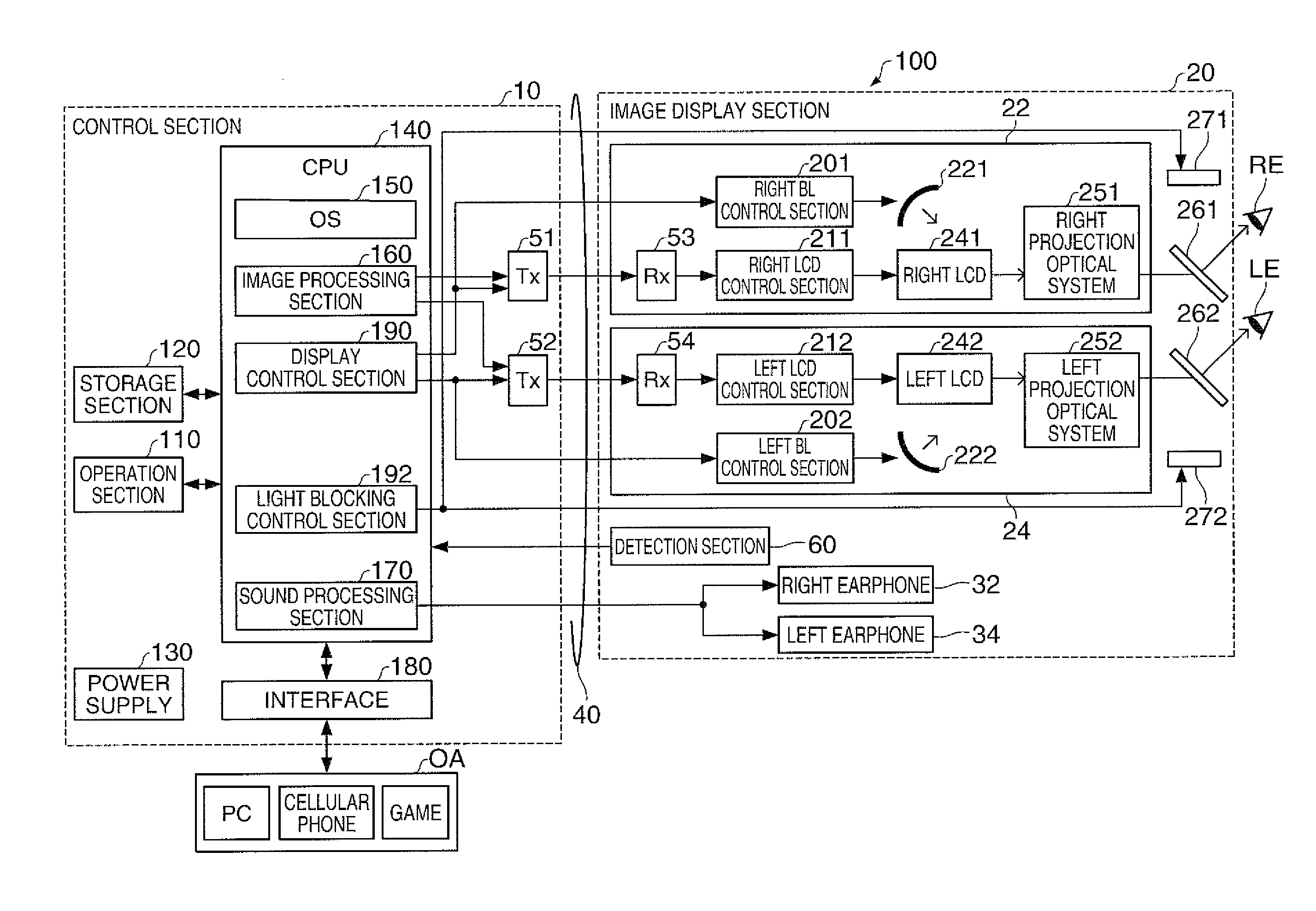
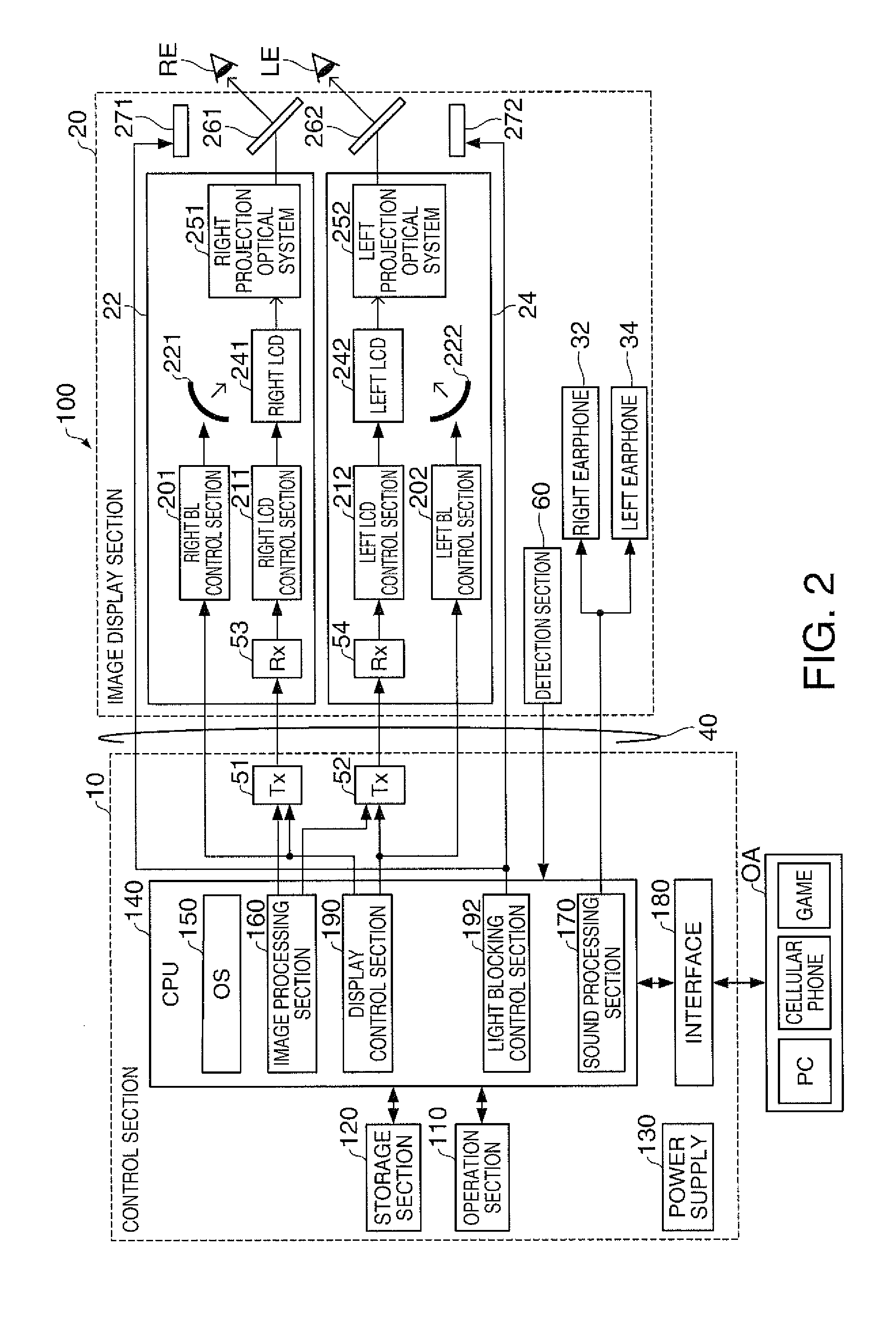
[0027]The head-mount type display device 100 is a display device to be mounted on the head, and is also called a head-mounted display (HMD). The head-mount type display device 100 according to the present embodiment is an optical transmission type (so called see-through type) head-mount type display device with which the virtual image is visually recognized, and at the same time the external sight (the external image) can directly be recognized visually.

[002...


PUM


Abstract

A head-mount type display device adapted to allow a user to visually recognize a virtual image in a state of being worn on the head of the user includes an image display section having an image light generation section adapted to generate an image light representing an image, a light blocking section adapted to transmit external light at a predetermined transmittance, and a virtual image forming section adapted to transmit the external light transmitted through the light blocking section and to form the virtual image in an eye of the user with the image light, and configured to allow the user to visually recognize the virtual image and an external image, an operation section with which the user inputs operation data, and a control section adapted to perform control of changing the transmittance of the light blocking section in accordance with operation data from the operation section.

Description

BACKGROUND[0001]1. Technical Field[0002]The present invention relates to a head-mount type display device for making the user visually recognize a virtual image in a state of being worn on the head of the user.[0003]2. Related Art[0004]In the past, there has been known a head-mount type display device for making the user visually recognize a virtual image in a state of being mounted on the head of the user. In such a head-mount type display device, there has been proposed a see-through head-mount type display device for superimposing the virtual image and the external image on each other (see, e.g., JP-A-2006-3879).[0005]In the see-through head mounted display of the related art, there is a problem that the external image can always be seen behind the virtual image, and therefore the external image acts as an obstacle and it becomes difficult to visually recognize the virtual image in the case of operating an object in the virtual image or gazing at a character and a graphics in the...

Claims


Application Information

Patent Timeline
02 Jun 2015
Publication
US9046686B2
IPC
G09G5/00; G02B27/01
CPC
G02B27/017; G02B2027/0178; G02B2027/0118; H04N21/4122; H04N21/431; H04N21/4884; G02B27/0172; G06F3/017
Inventors
SAITO, HITOSHI