
Inkjet nozzle device configured for venting gas bubbles

a technology of gas bubble venting and nozzle device, which is applied in the direction of printing, inking apparatus, etc., can solve the problems of inability to achieve perfect fluidic symmetry around the heater element, affecting the operation of the device, and requiring relatively complex fabrication methods. achieve the effect of fluid isolation, reduce backflow, and minimize the possibility of fluidic crosstalk between nearby objects

Active Publication Date: 2015-06-09
MEMJET TECH LTD
View PDF6 Cites 0 Cited by
  • Summary
  • Abstract
  • Description
  • Claims
  • Application Information

AI Technical Summary

Benefits of technology

[0024]A further advantage of the present invention is that each nozzle device is effectively fluidically isolated from nearby devices by virtue of the perimeter wall of the main chamber. The perimeter wall is typically a solid, continuous wall enclosing the main chamber and is absent any interruptions or openings. Hence, with only a floor inlet into the antechamber, there is a tortuous fluidic path between nearby devices. This, in combination with the advantageous reduction in backflow by virtue of the device geometry described above, minimizes the possibility of any fluidic crosstalk between nearby devices. By contrast, the arrangement of nozzle devices described in U.S. Pat. No. 7,857,428 suffers from fluidic crosstalk via the sidewall chamber entrances and the adjoining MEMS ink supply channel.
[0025]These and other advantages of the inkjet nozzle device according to the present invention will be readily apparent from the detailed description below.
[0026]Preferably, the baffle structure comprises a single baffle wall. Preferably, the baffle wall has a pair of side edges such that a gap extends between each side edge and the perimeter wall to define a pair of firing chamber entrances flanking the baffle wall, the firing chamber entrances being disposed symmetrically about the common plane of symmetry.
[0027]The baffle wall advantageously mirrors, as far as possible, an opposite end wall of the firing chamber. Hence, the baffle wall and the opposite end wall provide a similar reaction force to the bubble impulse during droplet ejection, notwithstanding the firing chamber entrances flanking the baffle wall.
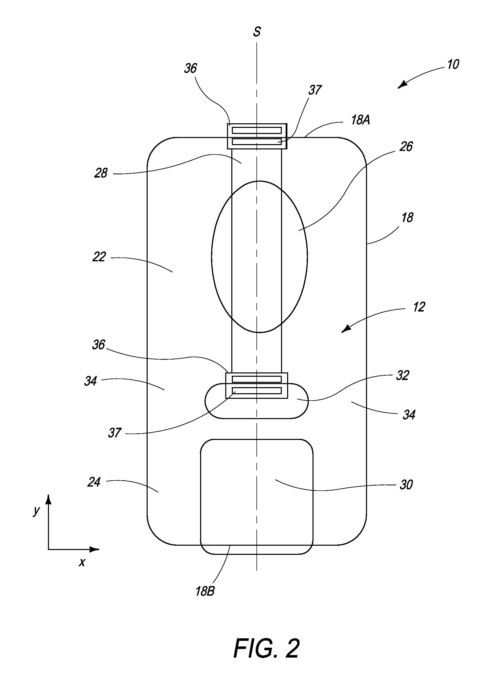
[0028]Preferably, the baffle wall is wider than the heater element. The width dimension is defined along the nominal x-axis of the main chamber. Preferably, the baffle wall occupies at least 30%, at least 40% or at least 50% of the width of the main chamber. Typically, the baffle wall occupies about half the width of the main chamber, with the firing chamber entrances flanking the baffle wall on either side thereof. The baffle wall usually has a width dimension (along the x-axis), which is greater than a thickness dimension (along the y-axis). Typically, the width of the baffle wall is at least two times greater or at least three time greater than the thickness of the baffle wall.
[0029]Preferably, the nozzle aperture is elongate having a longitudinal axis aligned with the plane of symmetry. Preferably, the nozzle aperture is elliptical having a major axis aligned with the plane of symmetry.

Problems solved by technology

Perfect fluidic symmetry around the heater element is not possible unless the heater element is suspended directly over the inlet to the nozzle chamber.
However, devices having a heater element suspended over the chamber inlet require relatively complex fabrication methods and are less robust than devices having bonded heater elements.
Furthermore, these devices suffer from a relatively high rate of backflow through the chamber inlet during ink ejection (resulting in inefficiencies), as well as potential printhead face flooding during chamber refilling by virtue of the alignment of the inlet and the nozzle aperture.
However, the arrangement described in U.S. Pat. No. 7,857,428 suffers from the disadvantages of relatively slow chamber refill rates and fluidic crosstalk between nearby nozzle chambers.
In addition, the arrangement described in U.S. Pat. No. 7,857,428 inevitably introduces a degree of asymmetry into droplet ejection compared to the arrangement described in U.S. Pat. No. 6,755,509.
This results in skewed droplet ejection trajectories as well as a reduction in efficiency.
However, this measure is not viable in high-speed printers, because it inevitably reduces chamber refill rates due to the increased flow resistance.
Furthermore, the high density of nozzle devices in a typical pagewidth printhead poses a thermal management problem: the ejection energy per drop ejected must be low enough to operate in so-called ‘self-cooling’ mode—that is, the chip temperature equilibrates to a steady state temperature well below the boiling point of the ink via removal of heat by ejected ink droplets.
However, multiple passivation and cavitation layers are incompatible with low-energy ‘self-cooling’ inkjet nozzle devices.
The relatively thick protective layers absorb too much energy and require drive energies which are too high for efficient self-cooling operation.
This places constraints on nozzle chamber designs for a target drop ejection volume.

Method used


Image

  • Inkjet nozzle device configured for venting gas bubbles
  • Inkjet nozzle device configured for venting gas bubbles
  • Inkjet nozzle device configured for venting gas bubbles

Examples


Embodiment Construction

Device Geometry

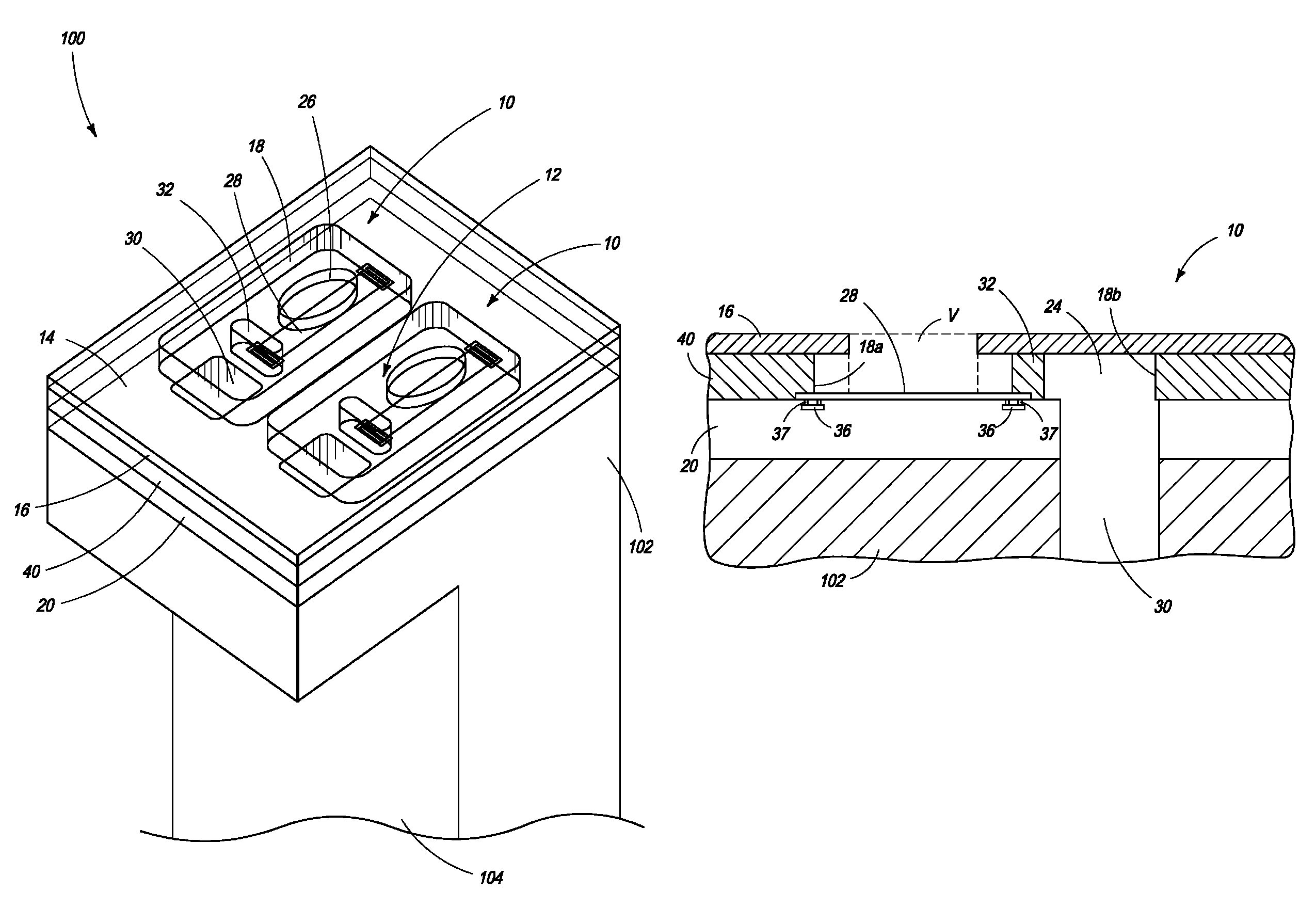
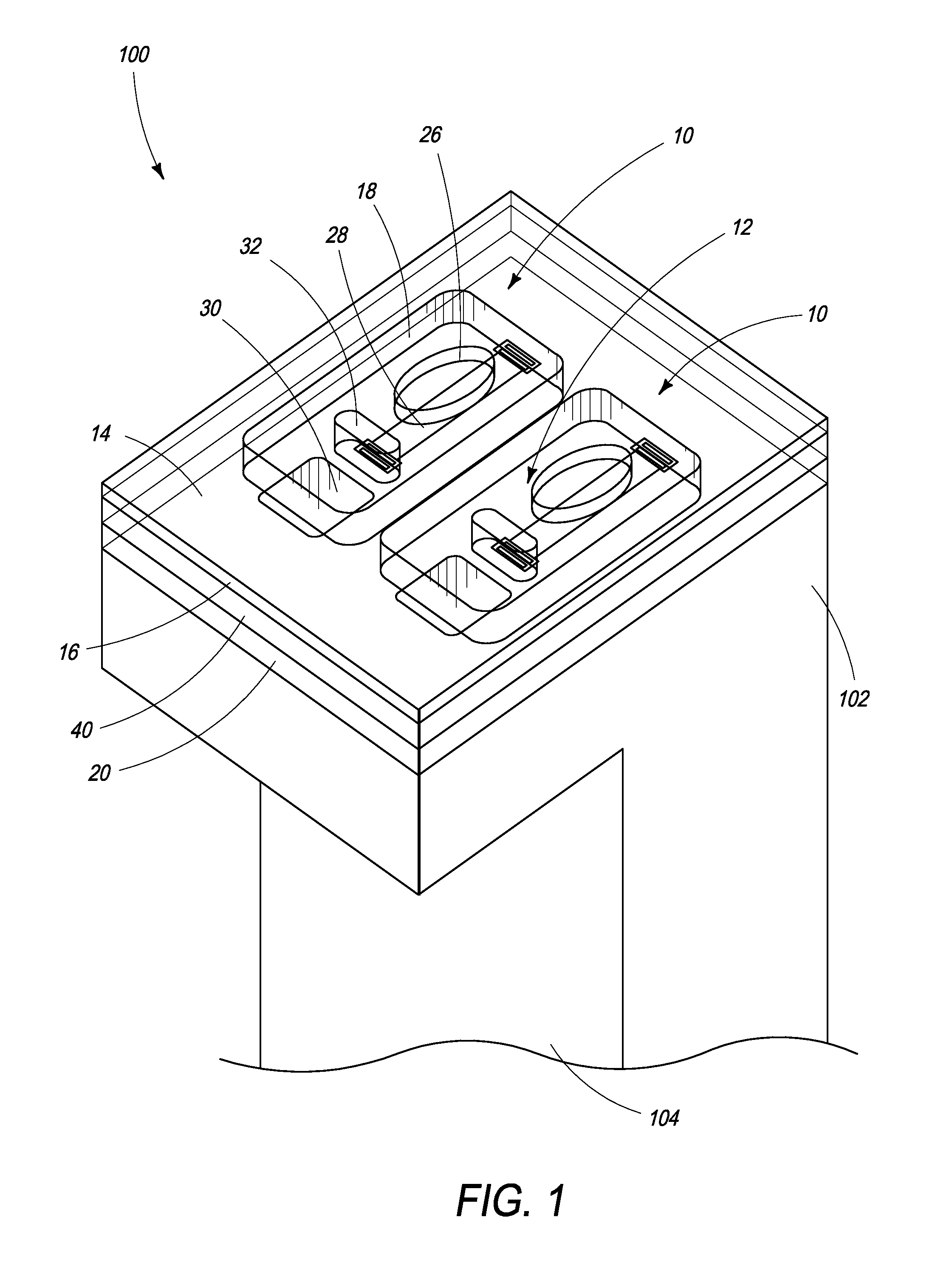
[0070]Referring to FIGS. 1 to 3, there is shown an inkjet nozzle device 10 according to the present invention. The inkjet nozzle device comprises a main chamber 12 having a floor 14, a roof 16 and a perimeter wall 18 extending between the floor and the roof. Typically, the floor is defined by a passivation layer covering a CMOS layer 20 containing drive circuitry for each actuator of the printhead. FIG. 1 shows the CMOS layer 20, which may comprise a plurality of metal layers interspersed with interlayer dielectric (ILD) layers.

[0071]In FIG. 1 the roof 16 is shown as a transparent layer so as to reveal details of each nozzle device 10. Typically, the roof 16 is comprised of a material, such as silicon dioxide or silicon nitride.

[0072]Referring now to FIG. 2, the main chamber 12 of the nozzle device 10 comprises a firing chamber 22 and an antechamber 24. The firing chamber 22 comprises a nozzle aperture 26 defined in the roof 16 and an actuator in the form of a resisti...


PUM


Abstract

An inkjet nozzle device configured for venting a gas bubble during droplet ejection. The inkjet nozzle device includes: a firing chamber for containing ink, the firing chamber having a floor and a roof defining an elongate nozzle aperture having a perimeter; and an elongate heater element bonded to the floor of the firing chamber, the heater element and nozzle aperture having aligned longitudinal axes. The device is configured to satisfy the relationships A=swept volume / area of heater element=8 to 14 microns; and B=firing chamber volume / swept volume=2 to 6. The swept volume is defined as the volume of a shape defined by a projection from the perimeter of the nozzle aperture to the floor of the firing chamber, and includes a volume contained within the nozzle aperture.

Description

[0001]This application is a Continuation-in-Part Application of U.S. application Ser. No. 14 / 310,353 filed on Jun. 20, 2014 which claims priority to U.S. Provisional Application 61 / 859,889 filed Jul. 30, 2013, the contents of which are incorporated herein by referenceFIELD OF THE INVENTION[0002]This invention relates to inkjet nozzle devices for inkjet printheads. It has been developed primarily to minimize cavitation damage to heater elements, improve thermal efficiency and increase printhead lifetimes.BACKGROUND OF THE INVENTION[0003]The Applicant has developed a range of Memjet® inkjet printers as described in, for example, WO2011 / 143700, WO2011 / 143699 and WO2009 / 089567, the contents of which are herein incorporated by reference. Memjet® printers employ a stationary pagewidth printhead in combination with a feed mechanism which feeds print media past the printhead in a single pass. Memjet® printers therefore provide much higher printing speeds than conventional scanning inkjet pr...

Claims


Application Information

Patent Timeline
Patent Type & Authority Patents(United States)
IPC IPC(8): B41J2/14B41J2/16
CPCB41J2/14088B41J2/14032B41J2/14016B41J2/1404B41J2/14129B41J2002/14169B41J2002/14475B41J2202/07B41J2202/18
Inventor NORTH, ANGUS JOHNMALLINSON, SAMUEL GEORGEFISHBURN, JENNIFER MIA
Owner MEMJET TECH LTD
Learn More