Inkjet nozzle device having high degree of symmetry

a nozzle device and high degree of symmetry technology, applied in the direction of printing, inking apparatus, etc., can solve the problems of less robust than devices with bonded heater elements, potential flooding of printhead faces, and devices with heater elements suspended over the chamber inlet, so as to reduce backflow, reduce the possibility of fluidic crosstalk between nearby areas, and effectively fluidically isolate

Active Publication Date: 2015-06-02
MEMJET TECH LTD
View PDF5 Cites 9 Cited by
  • Summary
  • Abstract
  • Description
  • Claims
  • Application Information

AI Technical Summary

Benefits of technology

The present invention is a nozzle device for inkjet printing that has several advantages over existing devices. Firstly, the device is designed to minimize fluidic crosstalk, which is the unwanted transfer of ink between nearby devices. This is achieved by using a perimeter wall that isolates each nozzle from nearby devices, creating a tortuous fluidic path between them. Secondly, the device design includes a baffle plate that mirrors the opposite end wall of the firing chamber, providing a similar reaction force during droplet ejection. Lastly, the device has a elongated nozzle aperture that aligns with the plane of symmetry, which further reduces the likelihood of fluidic crosstalk. These technical effects make the nozzle device more efficient and reliable for inkjet printing.

Problems solved by technology

However, devices having a heater element suspended over the chamber inlet require relatively complex fabrication methods and are less robust than devices having bonded heater elements.
Furthermore, these devices suffer from a relatively high rate of backflow through the chamber inlet during ink ejection (resulting in inefficiencies), as well as potential printhead face flooding during chamber refilling by virtue of the alignment of the inlet and the nozzle aperture.
However, the arrangement described in U.S. Pat. No. 7,857,428 suffers from the disadvantages of relatively slow chamber refill rates and fluidic crosstalk between nearby nozzle chambers.
In addition, the arrangement described in U.S. Pat. No. 7,857,428 inevitably introduces a degree of asymmetry into droplet ejection compared to the arrangement described in U.S. Pat. No. 6,755,509.
This results in skewed droplet ejection trajectories as well as a reduction in efficiency.
However, this measure is not viable in high-speed printers, because it inevitably reduces chamber refill rates due to the increased flow resistance.

Method used


Image

  • Inkjet nozzle device having high degree of symmetry
  • Inkjet nozzle device having high degree of symmetry
  • Inkjet nozzle device having high degree of symmetry

Examples


Embodiment Construction

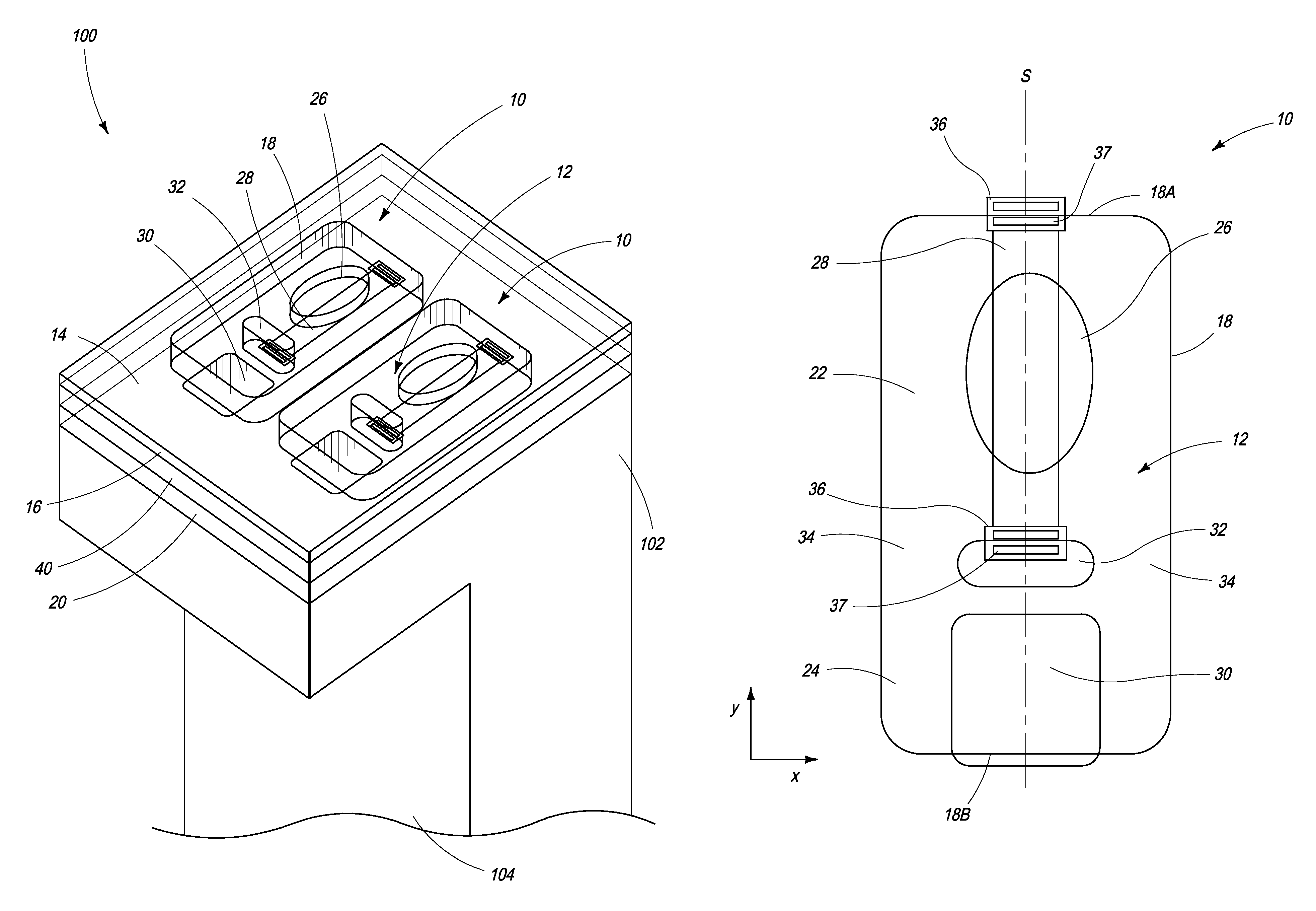
[0040]Referring to FIGS. 1 to 3, there is shown an inkjet nozzle device 10 according to the present invention. The inkjet nozzle device comprises a main chamber 12 having a floor 14, a roof 16 and a perimeter wall 18 extending between the floor and the roof. Typically, the floor is defined by a passivation layer covering a CMOS layer 20 containing drive circuitry for each actuator of the printhead. FIG. 1 shows the CMOS layer 20, which may comprise a plurality of metal layers interspersed with interlayer dielectric (ILD) layers.

[0041]In FIG. 1 the roof 16 is shown as a transparent layer so as to reveal details of each nozzle device 10. Typically, the roof 16 is comprised of a material, such as silicon dioxide or silicon nitride.

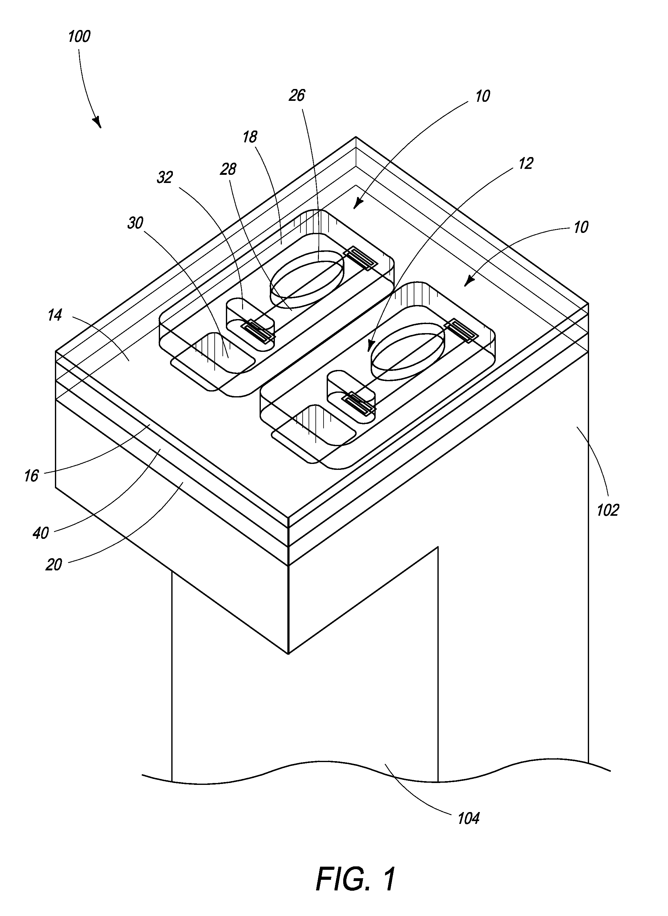
[0042]Referring now to FIG. 2, the main chamber 12 of the nozzle device 10 comprises a firing chamber 22 and an antechamber 24. The firing chamber 22 comprises a nozzle aperture 26 defined in the roof 16 and an actuator in the form of a resistive heater eleme...


PUM


Abstract

An inkjet nozzle device includes a main chamber having a floor, a roof and a perimeter wall extending between the floor and the roof. The main chamber includes: a firing chamber having a nozzle aperture defined in the roof and an actuator for ejection of ink through the nozzle aperture; an antechamber for supplying ink to the firing chamber, the antechamber having a main chamber inlet defined in the floor; and a baffle structure partitioning the main chamber to define the firing chamber and the antechamber, the baffle structure extending between the floor and the roof. The firing chamber and the antechamber have a common plane of symmetry.

Description

FIELD OF THE INVENTION[0001]This invention relates to inkjet nozzle devices for inkjet printheads. It has been developed primarily to improve droplet ejection trajectories and minimize fluidic crosstalk between devices, whilst maximizing chamber refill rates.BACKGROUND OF THE INVENTION[0002]The Applicant has developed a range of Memjet® inkjet printers as described in, for example, WO2011 / 143700, WO2011 / 143699 and WO2009 / 089567, the contents of which are herein incorporated by reference. Memjet® printers employ a stationary pagewidth printhead in combination with a feed mechanism which feeds print media past the printhead in a single pass. Memjet® printers therefore provide much higher printing speeds than conventional scanning inkjet printers.[0003]An inkjet printhead is comprised of a plurality (typically thousands) of individual inkjet nozzle devices, each supplied with ink. Each inkjet nozzle device typically comprises a nozzle chamber having a nozzle aperture and an actuator fo...

Claims


Application Information

Patent Timeline
Patent Type & Authority Patents(United States)
IPC IPC(8): B41J2/14B41J2/16
CPCB41J2/1433B41J2/14032B41J2/1404B41J2202/18B41J2/14088
Inventor NORTH, ANGUS JOHN
Owner MEMJET TECH LTD
Why Eureka
Try Eureka