
Inkjet nozzle device with symmetrically constrained bubble formation

a symmetrical constraint and nozzle technology, applied in the direction of printing, inking apparatus, etc., can solve the problems of inability to achieve perfect fluidic symmetry around the heater element, affecting the stability of the device, and requiring relatively complex fabrication methods, so as to reduce the possibility of fluidic crosstalk between nearby objects, reduce backflow, and effectively fluidize the

Active Publication Date: 2015-04-07
MEMJET TECH LTD
View PDF5 Cites 1 Cited by
  • Summary
  • Abstract
  • Description
  • Claims
  • Application Information

AI Technical Summary

Benefits of technology

The present invention provides an inkjet nozzle device with a unique baffle structure that minimizes fluidic crosstalk and reduces backflow between neighboring devices. The baffle structure includes a single baffle plate with a pair of symmetrically arranged firing chamber entrances flanking the baffle plate. The baffle plate is wider than the heater element and occupies at least a portion of the width of the main chamber. The nozzle aperture is elongated or elliptical with a major axis aligned with the plane of symmetry. The perimeter wall of the main chamber is a solid, continuous wall enclosing the chamber without any interruptions or openings. The design features a tortuous fluidic path between nearby devices, reducing the likelihood of fluidic crosstalk and ensuring efficient droplet ejection.

Problems solved by technology

Perfect fluidic symmetry around the heater element is not possible unless the heater element is suspended directly over the inlet to the nozzle chamber.
However, devices having a heater element suspended over the chamber inlet require relatively complex fabrication methods and are less robust than devices having bonded heater elements.
Furthermore, these devices suffer from a relatively high rate of backflow through the chamber inlet during ink ejection (resulting in inefficiencies), as well as potential printhead face flooding during chamber refilling by virtue of the alignment of the inlet and the nozzle aperture.
However, the arrangement described in U.S. Pat. No. 7,857,428 suffers from the disadvantages of relatively slow chamber refill rates and fluidic crosstalk between nearby nozzle chambers.
In addition, the arrangement described in U.S. Pat. No. 7,857,428 inevitably introduces a degree of asymmetry into droplet ejection compared to the arrangement described in U.S. Pat. No. 6,755,509.
This results in skewed droplet ejection trajectories as well as a reduction in efficiency.
However, this measure is not viable in high-speed printers, because it inevitably reduces chamber refill rates due to the increased flow resistance.

Method used


Image

  • Inkjet nozzle device with symmetrically constrained bubble formation
  • Inkjet nozzle device with symmetrically constrained bubble formation
  • Inkjet nozzle device with symmetrically constrained bubble formation

Examples


Embodiment Construction

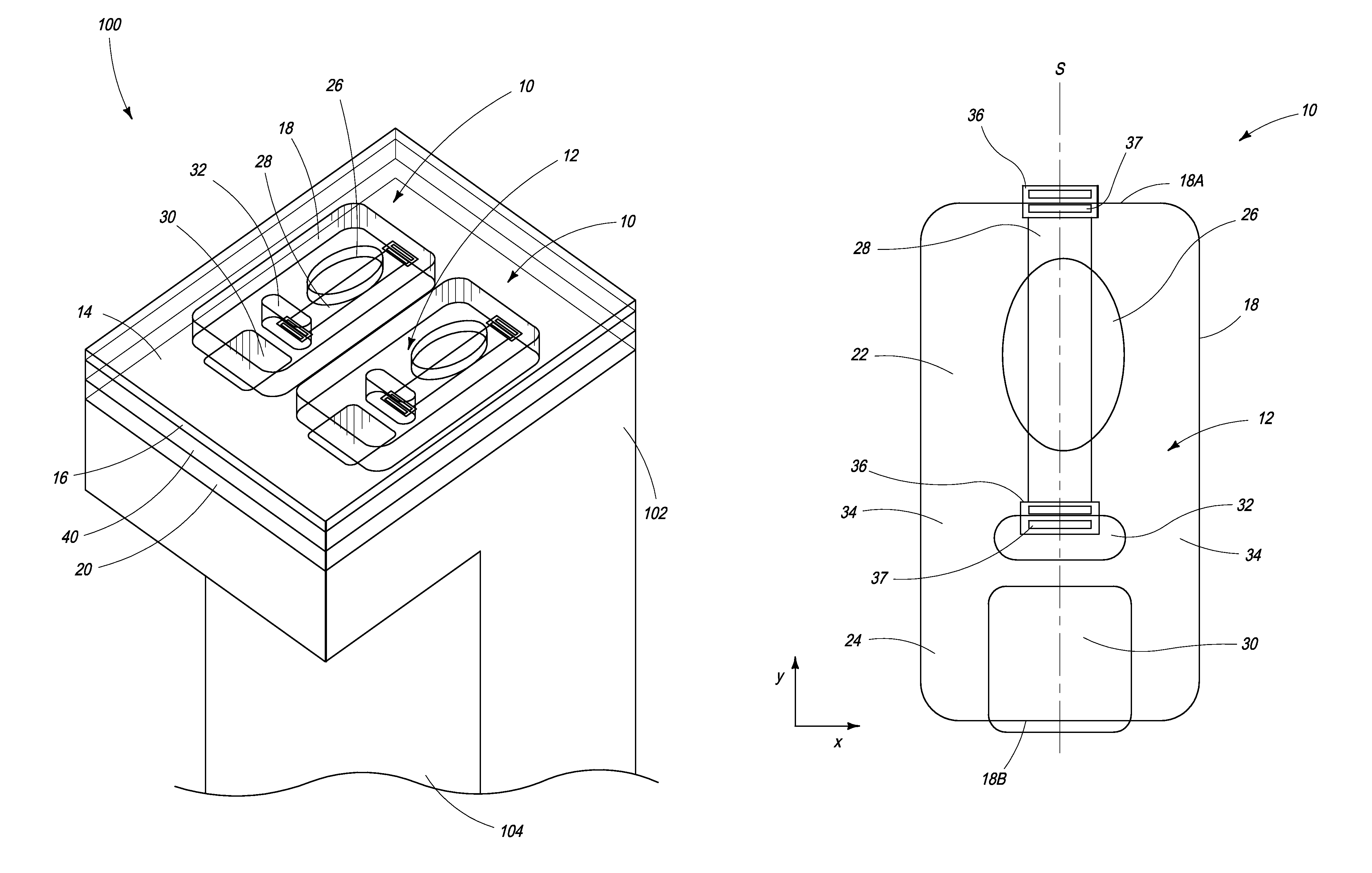
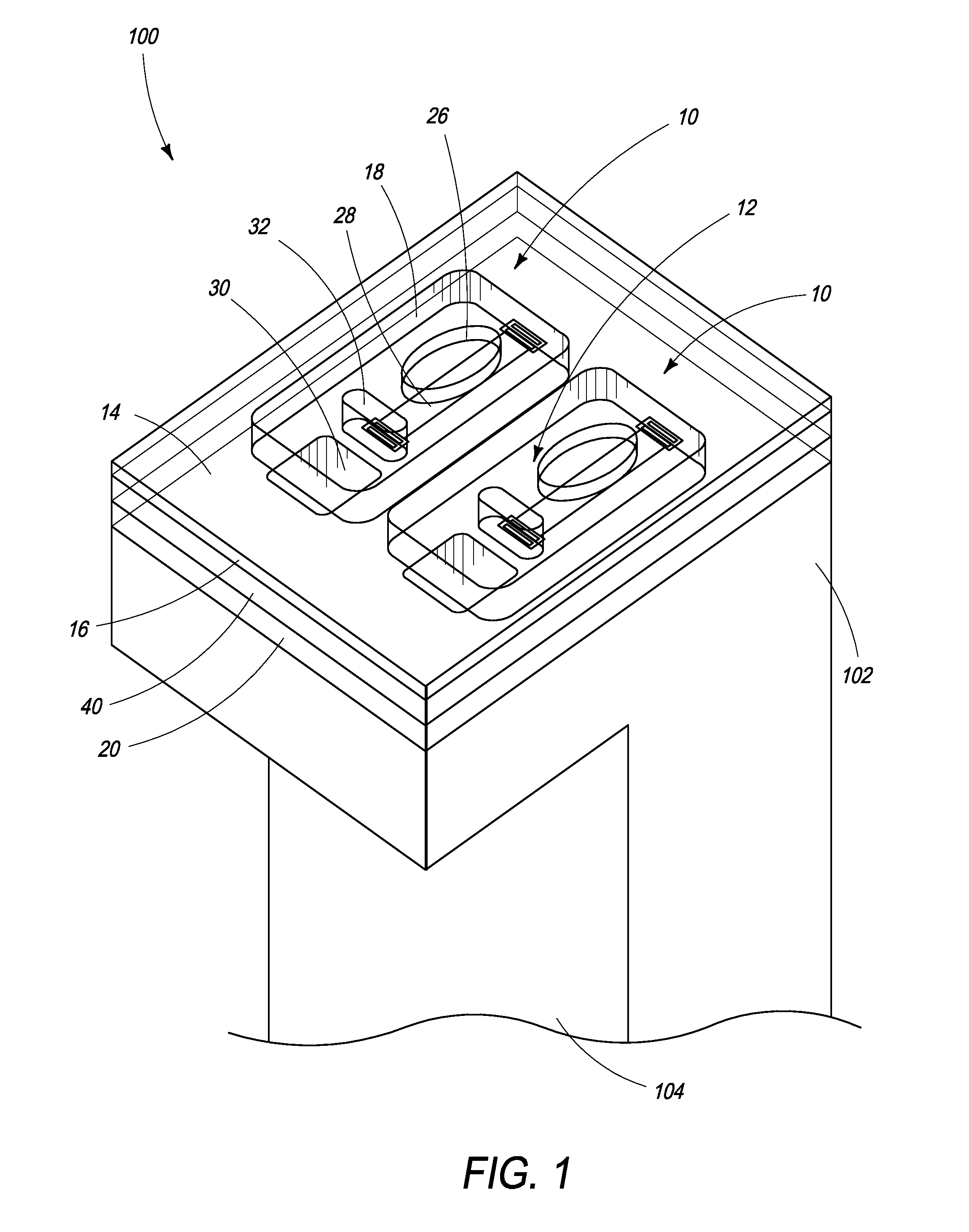
[0043]Referring to FIGS. 1 to 3, there is shown an inkjet nozzle device 10 according to the present invention. The inkjet nozzle device comprises a main chamber 12 having a floor 14, a roof 16 and a perimeter wall 18 extending between the floor and the roof. Typically, the floor is defined by a passivation layer covering a CMOS layer 20 containing drive circuitry for each actuator of the printhead. FIG. 1 shows the CMOS layer 20, which may comprise a plurality of metal layers interspersed with interlayer dielectric (ILD) layers.

[0044]In FIG. 1 the roof 16 is shown as a transparent layer so as to reveal details of each nozzle device 10. Typically, the roof 16 is comprised of a material, such as silicon dioxide or silicon nitride.

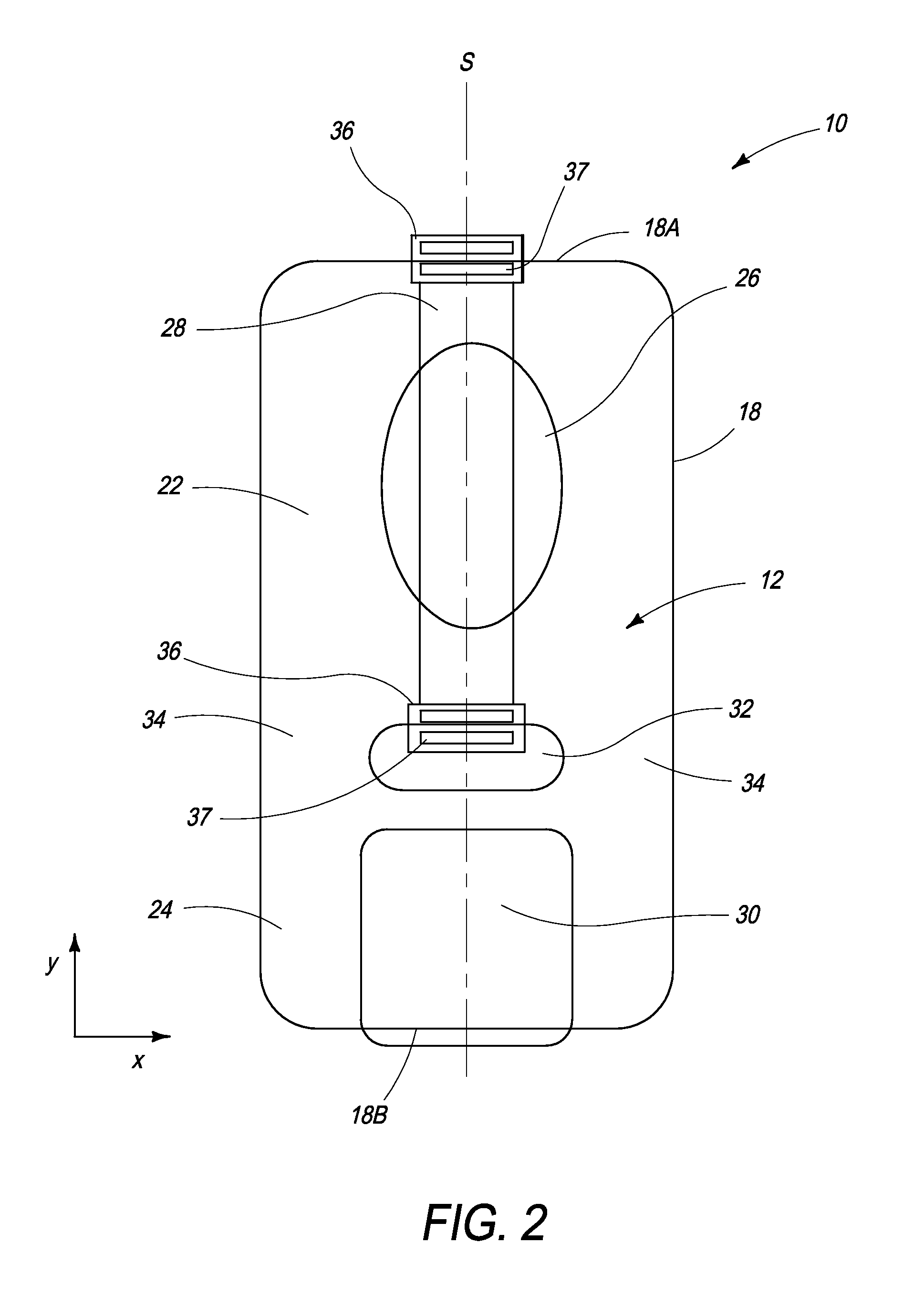
[0045]Referring now to FIG. 2, the main chamber 12 of the nozzle device 10 comprises a firing chamber 22 and an antechamber 24. The firing chamber 22 comprises a nozzle aperture 26 defined in the roof 16 and an actuator in the form of a resistive heater eleme...


PUM


Abstract

An inkjet nozzle device for symmetrically constrained bubble formation includes: a firing chamber having and an end wall, opposite sidewalls and a nozzle aperture defined in a roof thereof; a baffle plate positioned between the sidewalls of the firing chamber, such that a pair of firing chamber entrances are defined between side edges of the baffle plate and the sidewalls; and an elongate heating element bonded to a floor of the firing chamber, the heater element extending longitudinally between the baffle plate and the end wall. The baffle plate is wider than the heater element. Further, a centroid of the heater element coincides with a midpoint between the baffle plate and the end wall.

Description

RELATED APPLICATION[0001]This is a continuation of prior application Ser. No. 14 / 310,353, filed Jun. 20, 2014, entitled “INKJET NOZZLE DEVICE HAVING HIGH DEGREE OF SYMMETRY”, which is hereby incorporated in its entirety by reference herein.FIELD OF THE INVENTION[0002]This invention relates to inkjet nozzle devices for inkjet printheads. It has been developed primarily to improve droplet ejection trajectories and minimize fluidic crosstalk between devices, whilst maximizing chamber refill rates.BACKGROUND OF THE INVENTION[0003]The Applicant has developed a range of Memjet® inkjet printers as described in, for example, WO2011 / 143700, WO2011 / 143699 and WO2009 / 089567, the contents of which are herein incorporated by reference. Memjet® printers employ a stationary pagewidth printhead in combination with a feed mechanism which feeds print media past the printhead in a single pass. Memjet® printers therefore provide much higher printing speeds than conventional scanning inkjet printers.[00...

Claims


Application Information

Patent Timeline
Patent Type & Authority Patents(United States)
IPC IPC(8): B41J2/14B41J2/16
CPCB41J2/14032B41J2/14088B41J2/1404B41J2202/18B41J2/1433
Inventor NORTH, ANGUS JOHN
Owner MEMJET TECH LTD
Learn More