Cylinder lock with side bar and side pins, key and lock assembly

a technology of side bars and side pins, which is applied in the field of cylinder locks, can solve the problems of limited code movement, limited coding height, and limited coding heigh

Active Publication Date: 2015-06-09
ASSA OEM AB
View PDF17 Cites 7 Cited by
  • Summary
  • Abstract
  • Description
  • Claims
  • Application Information

AI Technical Summary

Benefits of technology

[0004]An aim of the invention is to provide a cylinder lock having more possibilities for coding. This is achieved through an improved use of the dimensions of the cylinder lock, so that the available space of the lock and of the key is employed to a larger extent.
[0005]The invention provides a cylinder lock comprising a cylinder housing provided with a key channel, or key-way, arranged in the cylinder housing, at least one latching bar arranged between the cylinder housing and the cylinder core and a plurality of side pins arranged on at least one side of the key channel and arranged to be lifted by an inserted key and in cooperation with the blocking bar allow or prevent relative rotation of the cylinder housing and the cylinder core. Each side pin is further provided with a foot adapted to be lifted by a groove in the side surface of the key. The foot of at least one of the side pins is tapered. In this way, enhanced coding possibilities are provided by means of making it possible to prolong the stroke of the coding pins in the cylinder core. Moreover, the inclination rise, or climbing, of the code pin along the key is facilitated. In this way, the variation in code level for a given distance along the key, such as the distance between two code pins, can be increased and thereby also the total number of code levels available along the key length.
[0007]In a preferred embodiment the tapered foot is conical. In this case, the foot comprises a tapering both against the key and the cylinder housing. This also facilitates rotation of the code pin, so that the foot can “roll” along the key when the key is inserted in through the key channel, and this rotation decrease the friction and thereby also the wear.

Problems solved by technology

Even if the height of the key is large, the possibility to employ this height is limited.
Also the space available for the code pins in the cylinder core limits the maximal movement of the code pins and thereby the space available for coding levels.

Method used


Image

  • Cylinder lock with side bar and side pins, key and lock assembly
  • Cylinder lock with side bar and side pins, key and lock assembly
  • Cylinder lock with side bar and side pins, key and lock assembly

Examples


Embodiment Construction

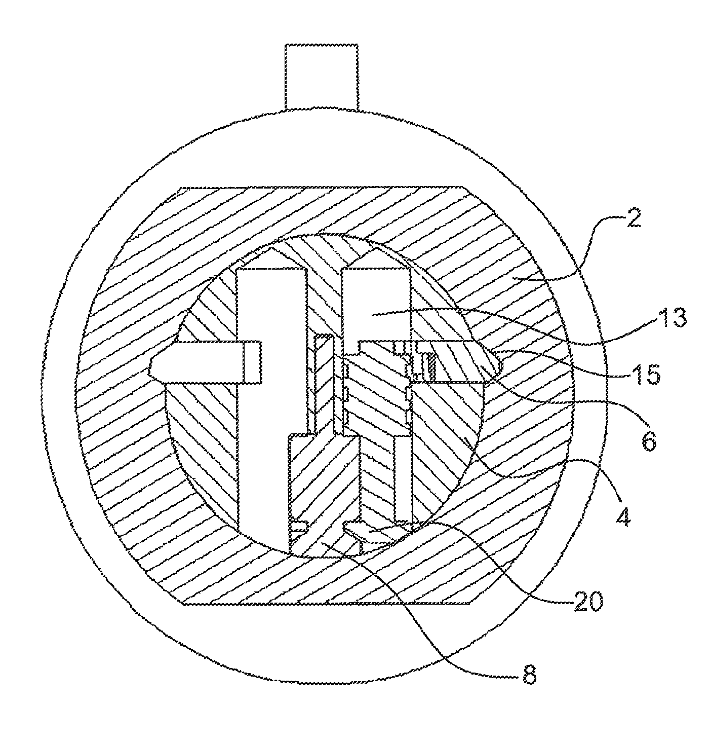
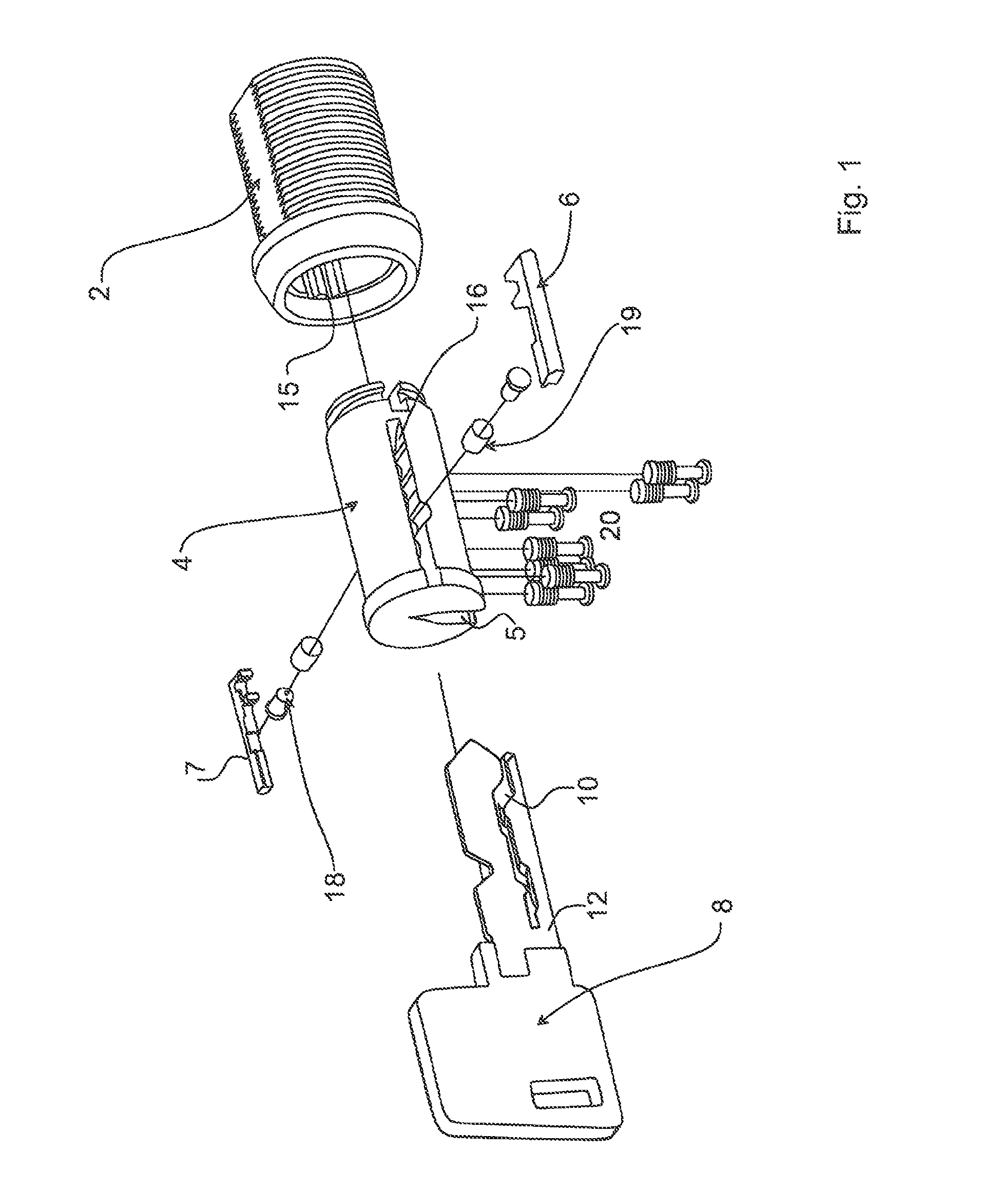
[0025]A first embodiment of a cylinder lock is illustrated in FIG. 1, which cylinder lock comprises a cylinder housing 2, a cylinder core 4 provided with a cylinder profile (key-way) or key channel 5, a plurality of side pins 20 and two side bars 6, 7 arranged on opposite sides of the key channel 5. The side bars 6, 7 are further arranged in recesses 15, 16 in the cylinder core 4 as well as in the cylinder housing 2 for baring or blocking their relative movement when the lock is locked, and the side bars 6, 7 are arranged to be pushed into the cylinder core 4, when the lock is being unlocked, out of engagement with the side bar recess 15 in the cylinder housing 2 so that the cylinder core 4 can rotate in relation to the cylinder housing. When the key is rotated, the side bars 6, 7 are pushed out from the respective side bar recess 15 in the direction towards the cylinder core. With the correct key, the side pins are lifted to correct code level and allows the movement of the side ba...


PUM


Abstract

A cylinder lock comprising a cylinder housing (2), a cylinder core (4) having a key channel (5) arranged in the cylinder housing (2), at least one side bar (6, 7) arranged between the cylinder housing (2) and the cylinder core (4) and a plurality of side pins (20) arranged on at least one side of the key channel (5) and arranged to be lifted by insertion of a key (8) and in cooperation with the side bar (6, 7) allow or prevent relative rotation of the cylinder housing (2) and the cylinder core (4), wherein each side pin (20) comprises a foot (26, 29) adapted to be lifted by a code groove (10) in the side surface (12) of the key. The cylinder lock is characterized in that the foot (26) of at least one of the side pins (20) is tapered. A key (8) for the cylinder lock having a groove for side pins having a tapered foot is also described.

Description

TECHNICAL FIELD[0001]The invention relates to a cylinder lock comprising side pins and a side bar arranged between the cylinder core and the cylinder house, and to keys for such cylinder locks.BACKGROUND AND PRIOR ART[0002]The invention relates to cylinder locks having side pins and side bar. Normally, this type of cylinder locks comprises a cylinder core and a cylinder housing, having the cylinder core arranged inside the cylinder housing and a side bar arranged in a space between the cylinder housing and the cylinder core. In a locked state, the side bar or blocking / latching bar is engaging and interfering with the cylinder housing and cylinder core and thereby prevents rotational movement of these in relation to each other. When the side pins are lifted by means of a key (code carrier) to a correct level by means of a groove in the side surface of the key, the side bar can be moved from engagement with the cylinder housing, and be pushed into the cylinder core and leave its locki...

Claims


Application Information

Patent Timeline
Patent Type & Authority Patents(United States)
IPC IPC(8): E05B19/06E05B27/06E05B27/00E05B27/10E05B19/00
CPCE05B27/0082E05B27/0017E05B19/0035Y10T70/7621Y10T70/7864
Inventor HERRMANN, JONAS
Owner ASSA OEM AB
Why Eureka
Try Eureka