Multi-function computer pointing device

Inactive Publication Date: 2009-04-30
FU LIANG
View PDF18 Cites 10 Cited by
  • Summary
  • Abstract
  • Description
  • Claims
  • Application Information

AI Technical Summary

Benefits of technology

[0098]The present invention has three aspects. The first aspect of the present invention includes an N-persistent-mode pointing device and a 2N-mixed-mode pointing device. The N-persistent-mode pointing device has N persistent modes and uses a simple momentary switch as the hardware component of the mode-selection means. The N-persistent-mode design of the present invention requires essentially the same number / type of hardware components as the prior art dual-mode designs but may have practically any desired number of modes and control practically any desired number of functions. As explained later, the N-persistent mode design of the present invention overcomes all disadvantages of the prior art single-mode designs, dual-mode designs, dominant-axis designs, and host-implemented methods. The 2N-mixed-mode design further expands the total modes to 2N and provides more flexibilities and possibilities. With essentially the same number / type of hardware components as the prior art dual-mode designs, the N-persistent-mode and 2N-mixed mode designs can practically any desired number of functions.
[0099]The second aspect of the present invention is an unconventional method for generating target-motion signals with common motion controls used in pointing devices. In contrast to conventional implementations, the present invention uses a qualification-rule-based dynamic mapping. The second aspect of the present invention provides more effective and efficient target motion control with the same hardware motion controls. As explained later, the qualification-rule-based dynamic mapping of the present invention overcomes all the disadvantages of the prior art static and dynamic mappings.
[0100]The third aspect of the present invention combines the multi-mode designs with the qualification-rule-based dynamic mapping of the second aspect of the present invention, taking their separate advantages and further generating combined advantages. This aspect of the present invention allows using different mappings for different motion control and motion function pairs, hence solves the problem of incompatible motion functions. The final result is an N-persistent-mode or a 2N-mixed-mode pointing device that controls more functions, controls each function more effectively and efficiently, and / or requires fewer components. As explained later, the third aspect of the present invention overcomes all disadvantages of the prior art multi-function pointing devices.

Problems solved by technology

However, a pointing device usually may have only one such motion control.
But the problem is that, with static mapping, the mouse motion control may not be effective and / or efficient for other types of motion functions.
The most significant disadvantage of mouse motion control with static mapping is that large amount / fast / continuous target motion requires large amount / fast / continuous mouse motion.
So simply use a mouse motion control with static mappings for both cursor and scroll control, as suggested by some of the prior art dual-mode designs, would not provide effective and efficient scroll control in all situations.
The fast motion means that the available working space is used up quickly, which forces the user to reposition the pointing device even more frequently.
Frequent reposition of the pointing device not only is tedious but also stops the scroll in the mean time.
That results a very ineffective and inefficient scroll control.
In fact, if both modes used static mapping, as suggested by most of the prior art dual-mode designs, the scroll control would be ineffective and / or inefficient.

Method used


Image

  • Multi-function computer pointing device
  • Multi-function computer pointing device
  • Multi-function computer pointing device

Examples


Embodiment Construction

—PREFERRED EMBODIMENTS OF THE FIRST ASPECT OF THE PRESENT INVENTION

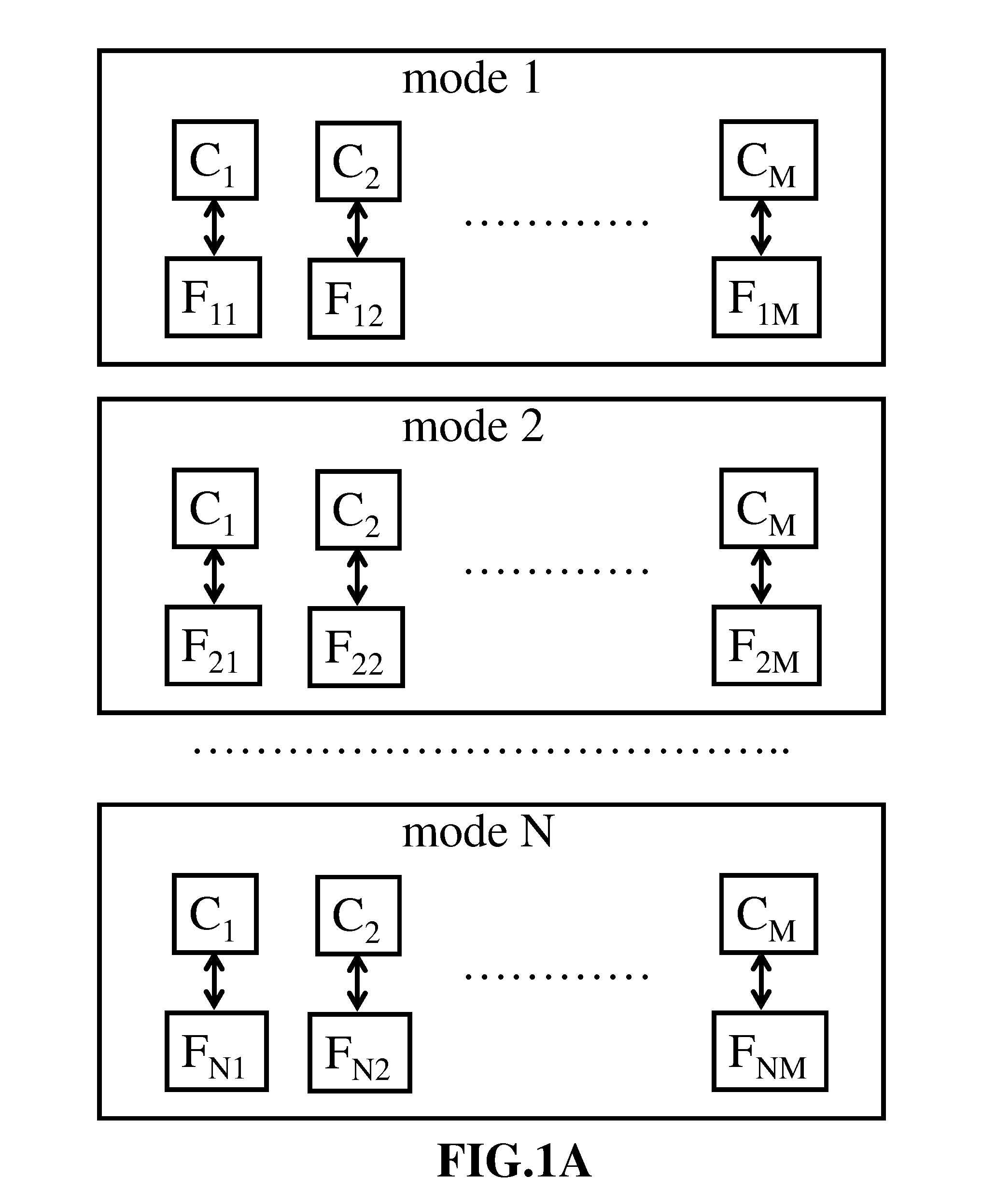
[0127]The first aspect of the present invention includes an N-persistent-mode pointing device and a 2N-mixed-mode pointing device. For the N-persistent-mode pointing device of the present invention, an N-persistent-mode correspondence is established where each control is assigned to control a specific (suitable) function in each persistent mode. FIG. 1A depicts the N-persistent-mode correspondence for M controls (C1,C2, . . . CM) to control up to N×M functions (F11,F12, . . . FNM). Some of these functions may be redundant or null functions (the corresponding control in the corresponding mode has no effect). Each double-headed arrow in FIG. 1A represents a specific mapping between a specific pair of control and function. With this arrangement, the N-persistent-mode pointing device of the present invention may control as many as N times functions as a single-mode design with same number / type of controls. Construction o...


PUM


Abstract

A first aspect of the present invention includes an N-persistent-mode pointing device and a 2N-mixed-mode pointing device. A second aspect of the present invention is an unconventional method for generating target-motion signals with common motion controls. This method utilizes a qualification-rule-based dynamic mapping of the present invention. A third aspect of the present invention combines the multi-mode designs and the dynamic mapping.

Description

CROSS-REFERENCE TO RELATED APPLICATIONS[0001]Not ApplicableFEDERALY SPONSORED RESEARCH[0002]Not ApplicableSEQUENCE LISTING OR PROGRAM[0003]Not ApplicableBACKGROUND OF THE INVENTION[0004]1. Field of Invention[0005]This invention relates to pointing devices, especially multi-dimensional and multi-function pointing devices.[0006]2. Prior Art[0007]Pointing device and Graphical User Interface (GUI) provide convenient interface for people to interact with computers and other types of equipment. The most popular pointing devices include mouse, trackball, touch pad, and joystick (or the like). Pointing devices often comprise two types of user operable controls, namely, button control and motion control. A Button control detects the activation and deactivation (e.g., press and release) caused by user and generates simple on and off button-control signals accordingly. A button control may comprise a simple mechanical switch or one or more sensors. A motion control detects certain type(s) of m...

Claims


Application Information

Patent Timeline
IPC IPC(8): G09G5/00
CPCG06F3/038
Inventor FU, LIANG
Owner FU LIANG
Why Eureka
Try Eureka