Pres-control type sliding rail assembly

a technology of sliding rails and assembly parts, which is applied in the direction of drawers, furniture parts, domestic applications, etc., can solve the problems of inconvenient detachment of inability to detach drawers from drawer cabinets, etc., and achieves simple structure, prevent falling, and facilitate mounting and dismounting.

Active Publication Date: 2015-06-16
NAN JUEN INT CO LTD
View PDF9 Cites 4 Cited by
  • Summary
  • Abstract
  • Description
  • Claims
  • Application Information

AI Technical Summary

Benefits of technology

[0005]The present invention has been accomplished under the circumstances in view. It is the main object of the present invention to provide a press-control type sliding rail assembly, which is highly detachable, facilitating mounting and dismounting, allowing quick removal of the drawer from the drawer cabinet and preventing falling of the component parts during application.
[0007]Thus, the limiter member can be biased relative to the intermediate rail to move the first stop flange and the second stop flange in reversed directions. When the second stop flange is pressed by an external force to move the first stop flange in direction away from the intermediate rail toward the inner rail, the first stop flange can stop the stop block, preventing falling of the inner rail out of the intermediate rail. Therefore, the press-control type sliding rail assembly of the invention has a simple structure and facilitates mounting and dismounting.

Problems solved by technology

If the two stop members of the two sliding rail assemblies are not accurately biased to the unlocking position, the user cannot detach the drawer from the drawer cabinet.
Thus, it is inconvenient to detach the drawer from the drawer cabinet.

Method used


Image

  • Pres-control type sliding rail assembly
  • Pres-control type sliding rail assembly
  • Pres-control type sliding rail assembly

Examples


Embodiment Construction

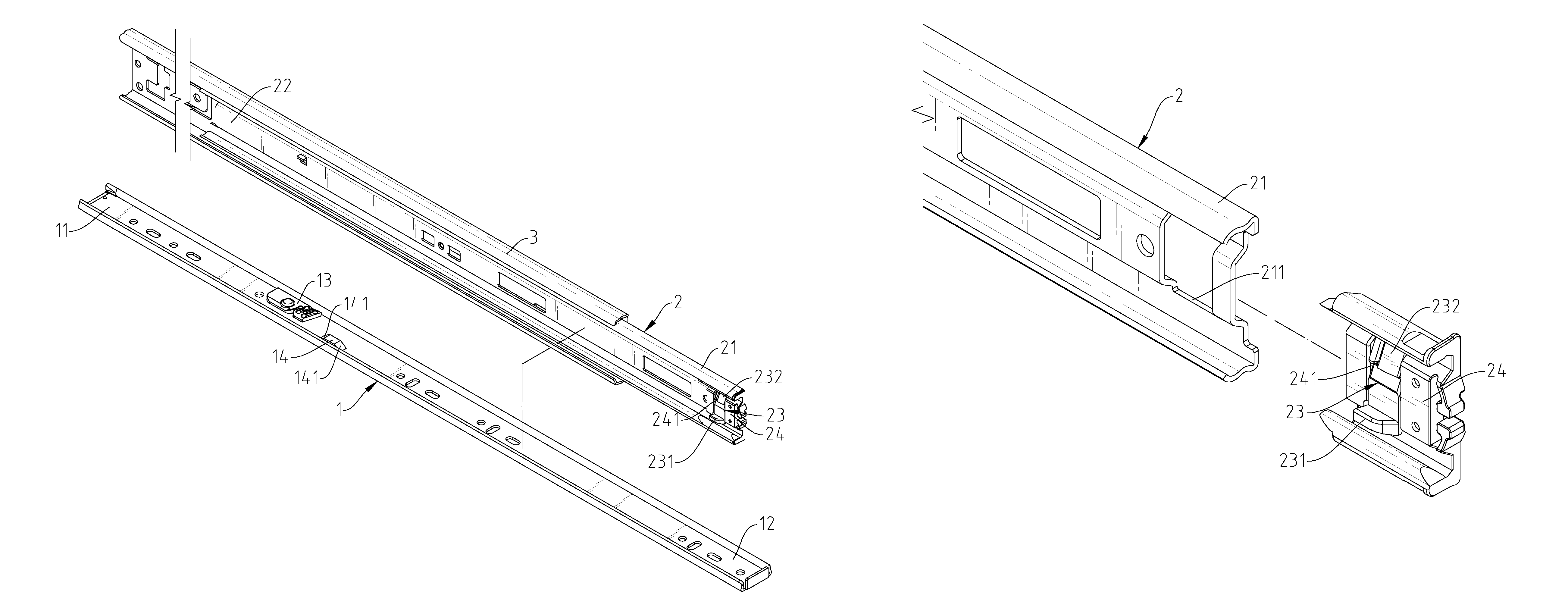
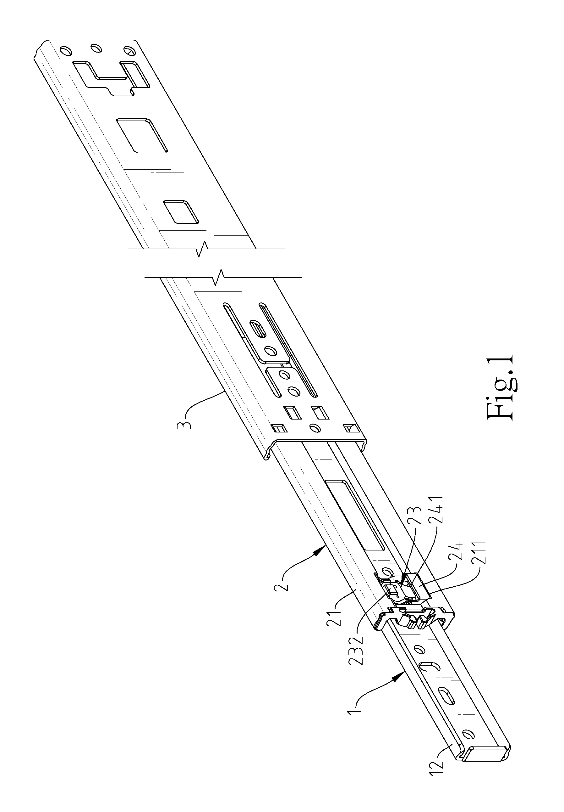
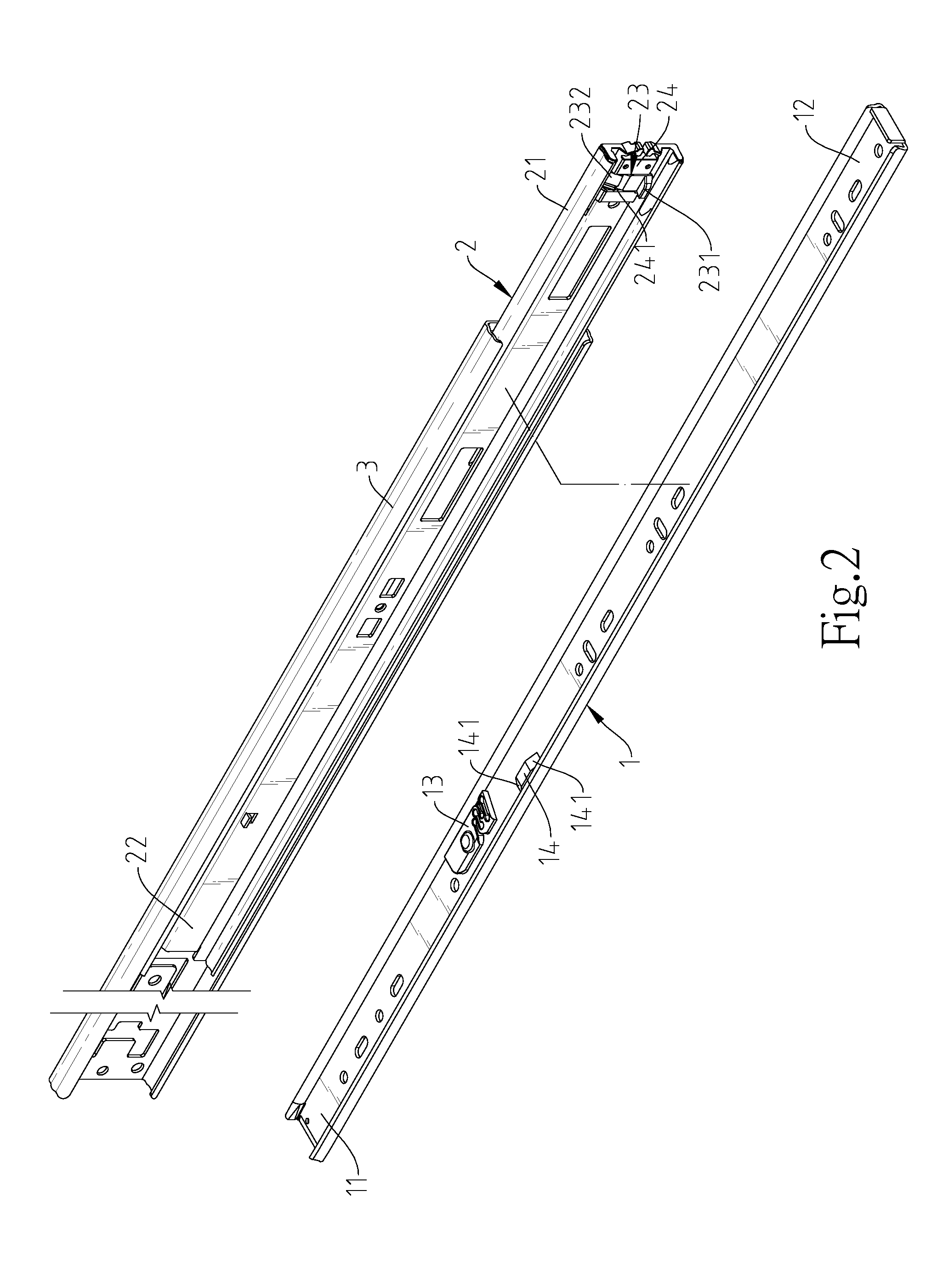
[0018]Referring to FIGS. 1-4, a press-control type sliding rail assembly in accordance with the present invention is shown comprising an inner rail 1, an intermediate rail 2 and an outer rail 3. The intermediate rail 2 is coupled between the inner rail 1 and the outer rail 2 in such a manner that the inner rail 1 can be moved in and out of the intermediate rail 2, and the intermediate rail 2 can be moved in and out of the outer rail 3.

[0019]The inner rail 1 comprises opposing first position-limit end 11 and first mounting end 12, a stop block 13 located at a lower side of the inner wall thereof and spaced between the first position-limit end 11 and first mounting end 12, and a push block 14 located at an upper side of the same inner wall and disposed adjacent to the push block 14 and spaced between the stop block 13 and the first mounting end 12. Further, the push block 14 defines a beveled guide face 141 at each of opposing front and rear sides thereof.

[0020]The intermediate rail 2...


PUM


Abstract

A press-control type sliding rail assembly includes an intermediate rail, an inner rail slidably coupled to the intermediate rail, a limiter member pivotally mounted at the intermediate rail and defining opposing first stop flange and second stop flange, and a stop block located at the inner rail for stopping against the first stop flange to prevent falling of the inner rail out of the intermediate rail when the second stop flange is pressed by an external force to bias the limiter member in moving the first stop flange toward the inner rail.

Description

BACKGROUND OF THE INVENTION[0001]1. Field of the Invention[0002]The present invention relates to a sliding rail assembly for coupling between a drawer and a drawer cabinet and more particularly, to a press-control type sliding rail assembly that facilitates mounting and dismounting and prevents falling of the inner rail out of the intermediate rail.[0003]2. Description of the Related Art[0004]Sliding rail assemblies are widely used with drawers in drawer cabinets for allowing the drawers to be smoothly moved in and out respective drawer cabinets. To facilitate application and cleaning, detachable multi-rail type sliding rail assemblies are created. A detachable multi-rail type sliding rail assembly has a stop member provided between the inner rail and the outer rail to prohibit falling of the inner rail with the drawer out of the outer rail when the drawer is pulled out of the drawer cabinet. When going to detach the drawer from the drawer cabinet, the user must manually bias the st...

Claims


Application Information

Patent Timeline
Patent Type & Authority Patents(United States)
IPC IPC(8): A47B88/16A47B88/04A47B88/49
CPCA47B88/16A47B88/0418A47B2210/0016A47B2088/0444A47B88/423A47B2088/4235A47B88/57
Inventor CHIU, I-HSIANG
Owner NAN JUEN INT CO LTD
Why Eureka
Try Eureka